Railroad Forums 

  • Catenary on your layouts

  • Discussion related to everything about model railroading, from layout design and planning, to reviews of related model tools and equipment. Discussion includes O, S, HO, N and Z, as well as narrow gauge topics. Also includes discussion of traditional "toy train" and "collector" topics such as Lionel, American Flyer, Marx, and others. Also includes discussion of outdoor garden railways and live steamers.
Discussion related to everything about model railroading, from layout design and planning, to reviews of related model tools and equipment. Discussion includes O, S, HO, N and Z, as well as narrow gauge topics. Also includes discussion of traditional "toy train" and "collector" topics such as Lionel, American Flyer, Marx, and others. Also includes discussion of outdoor garden railways and live steamers.

Moderators: 3rdrail, stilson4283, Otto Vondrak

 #784380  by Otto Vondrak
 
green_elite_cab wrote:i was looking for a small electric i could make a free-lance engine out of. I have a book with plans for this locomotive, but it looks like a tough build.

Cannonball Shops made a simple steeplecab shell that would slip over the Bachmann 44-tonner... might be a less expensive way to go if you don't want to invest a lot... Not sure if they are still available, though.

http://www.mrrwarehouse.com/MRW-Made/steeple.htm

Also on that page is an ad for a brass kit for a Baldwin centercab, similar to NH electrics.

-otto-
 #784437  by green_elite_cab
 
Otto Vondrak wrote:
green_elite_cab wrote:i was looking for a small electric i could make a free-lance engine out of. I have a book with plans for this locomotive, but it looks like a tough build.

Cannonball Shops made a simple steeplecab shell that would slip over the Bachmann 44-tonner... might be a less expensive way to go if you don't want to invest a lot... Not sure if they are still available, though.

http://www.mrrwarehouse.com/MRW-Made/steeple.htm

Also on that page is an ad for a brass kit for a Baldwin centercab, similar to NH electrics.

-otto-
Yeah, i would have preferred the Baldwin Centercabs, but i can't seem to find those easily either.
 #786084  by ac0catenary
 
Thats a awesome pict.. I love the NH style concrete tower complete with accurate tower number. First time I ever seen a EF-1 model
 #786114  by green_elite_cab
 
I got a little bit more week done on my catenary system. I added some of the wire cross spans and steady rods.

A friend of mine also made me this awesome punch-jig that cuts wire and forms it into the grab irons for the catenary pole, so i can mass produce them quickly and easily.
 #786717  by green_elite_cab
 
Here is what i've done recently. I've put in the hangers and steady spans for the two bridges i built. I also punched out a few more grab irons, but i need 32 for the long poles (for each pole, 64 for a whole bridge. "standard" bridges need at least half that, luckily). I'm going to have to pick up more brass wire.

There is some question as to whether or not the hangers go all the way down to the steady span on K-brace spans. I've seen it where the hangers ONLY attach to the Messenger wire (the curvy wire), but i've also seen hangers do go down to the steady span. In most of my books, its to hard to really tell. You can kind of see the clips on the steady wire, but the wire itself is often obscure. If there is a general consensus on what is more common, i suppose i can easily change the setup i have now (just snip the wire and unsolder the other end)

Image

This is the jig a friend made me for making the grab irons for each bridge. They might need a little tweaking before installation, but i don't have to eye ball it and play games. I can just punch the wires and bend them.

Image
 #795358  by green_elite_cab
 
Otto Vondrak wrote:Cool stuff. You should write this up and take pictures along the way... it would make a good story for this site...

-otto-


I'd love to contribute! Right now it might take me a while, but starting May (when this semester ends) i should have much more time to work on the catenary.
ac0catenary wrote:Everyone I found this Surfing...check it out...Enjoy the PRR catenary feast !!

http://www.subchat.com/read.asp?Id=911182
That's a kick-@$$ site right there!
 #806913  by green_elite_cab
 
Alright, its been a month, but starting tommorow, i hope to begin constructing more bridges. I'm going to leave the details for later, only installing the insulators and such so i can begin hanging wires. Right now, the problem i'm having is i ran out of the brass wire i was using and i haven't been able to find a suitable replacement. I'm going to need a TON as well, since all those grab irons add up, and i go through them faster using the jig my friend made.

I should have enough material to construct at least 3 more catenary structures, possibly a fourth if i can reinforce an old IHC signal bridge kit to fit in a particular location (it is so light that the pantographs can push it out of alignment).


These new bridges will be special. They will have thicker cross beams, as is Pennsy policy on curves. They will also require lots of tweaking. There are a number of considerations:

1.) how far to offset the hangers on the catenary bridge. the wire is "banked" on curves, so the location where the hangers attach to the bridge and where the wires hang are offset from each other. luckily, on tight curves, elongated "clips" are not required between the trolley and auxiliary wire.

2.) How far to offset the wires. the Pantograph shoes of an HHP-8 and a GG1 follow totally different paths (the G's pans tend to be offset). I have to find the right distance so that their shoes can glide easily on the wire

I plan to fix this by putting attaching the hangers to the crossbeam, but not soldering the ends together. essentially, the "y" shape will not be completed (yet). I will then tweak the more "horizontal" wire that will hold the trolley wire until it looks like it is about right (after rolling a GG1 and some other electrics through), and then solder the other (supporting) end of the hanger, to complete the "y".

The transmission lines will also be offset on the top. On tighter curves, i've seen them move the outer-most transmission lines to one side (one example would be on the NY&LB (North Jersey Coastline) above the Outerbridge Crossing ramp. I figure this will also keep them safe from people bumping them ( I've already hit two transmission arms :wall1: ) It appears that on tight curves, the pennsy (or in the current case, NJ transit) alternated between the "standard" transmission arm set up, and the "double on one side" set up.

In the future, i'm going to have to modify these bridges and the ones i've installed a bit to accept the pull off wires of the crossovers they bracket. I think i can do that while i hang the wires after the bridges are solidly installed.

here is a diagram of approximately what the next two bridges will look like. I'll probably build two more of a similar design, though I'm banking on maybe creating some pure wire cross spans instead of all K-braces in the future.

Image

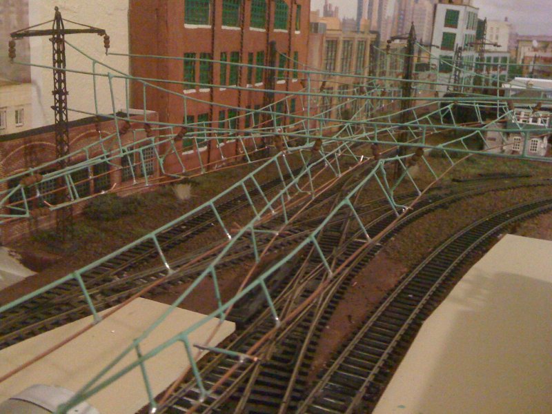
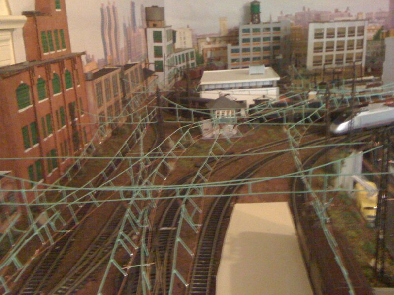
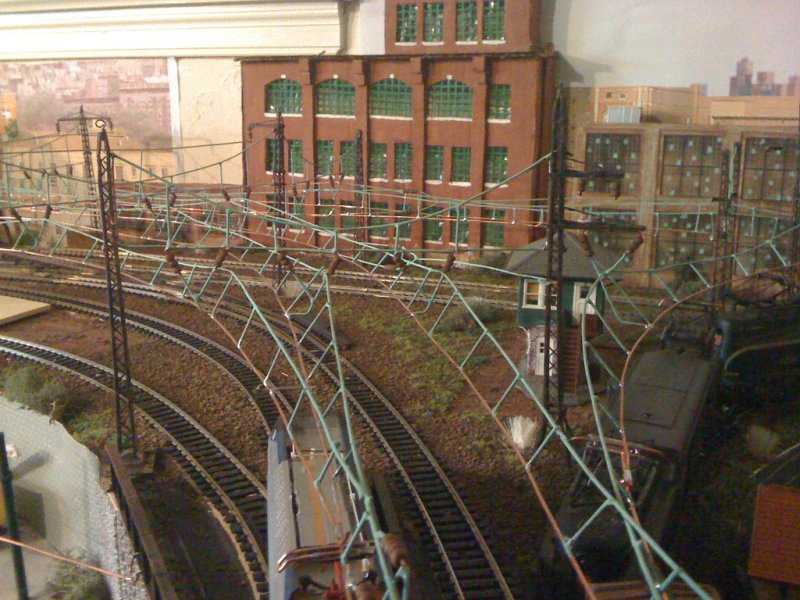
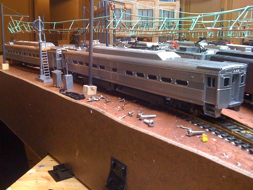
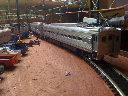
and just for the hell of it, here is a shot with my unfinished catenary bridges.

Image
 #806922  by cnj1524
 
Love the E44,anytime you want you can come to my machine shop,you got my vote,building it is ALOT of work
and Im very impressed with your turn outs,great job,I hope some of the pics I gave u helped
 #807143  by green_elite_cab
 
cnj1524 wrote:Love the E44,anytime you want you can come to my machine shop,you got my vote,building it is ALOT of work
and Im very impressed with your turn outs,great job,I hope some of the pics I gave u helped
They've helped me quite a bit actually. I frequently thumb through them, one of the photos was of the one side of E44A 4456, which i needed to finish painting that model (its apart right now because i need to add the decoder and pick-ups), and they also gave me a good view of E33 4608 when i was repainting that one. (i think i posted a photo of the model on the previous page). its the same with #4465. one photo you sent shows it still has Pennsy numbers and that radio equipped decal. right now, i'm trying to find matching number sets for it.

The shots of that signal bridge and crossovers are also useful, and I'm thinking about how i might be able to model that signal bridge. I can see that the catenary pull offs anchor right to the bridge, so it seems that i can mount them on the cross beams as well as the poles, which makes things convenient on my small layout.

they also helped me with updating my AEM7 and ALP44 models. Those shots of the resistor grids on those AEM7-ACs helped a bunch. I was able to see whats inside of them, and so i think found good stand in for the grids: Plastic screws with a fine thread. from the front, they look just about right, and behind the screening, no one really notices they are screws. I already made new resistor grids for my ALP44, and when i find some material that looks good enough, i'll try to make AEM7s that have the see-thru resistor grid boxes. TCS's DP2X decoder is so small that it can fit below the roof-line of the AEM7, so now is high time to update my models.

The new resistor grid on my ALP44. I might need to touch up the paint, but its a good start.

Image

Image
 #808331  by ac0catenary
 
Cab: are you going to install the signal line on your catenary poles?

For lining up inclined catenary its almost trial and error. I use the Y bracket and have a AEM7 and GG-1 (shortest to longest tracking) on the track I'm stringing catenary to gauge the sweet spot between the two. Thats my technique
These photos show wire span supported catenary, pull off wires and feeders. This section is in front of the stations so no High tension lines are present.
Image
Image
Image

I finally recieved two IHP silverliner IVs
Image
Image
  • 1
  • 8
  • 9
  • 10
  • 11
  • 12