• Scratchbuilding a Pantograph

  • Discussion related to everything about model railroading, from layout design and planning, to reviews of related model tools and equipment. Discussion includes O, S, HO, N and Z, as well as narrow gauge topics. Also includes discussion of traditional "toy train" and "collector" topics such as Lionel, American Flyer, Marx, and others. Also includes discussion of outdoor garden railways and live steamers.
Discussion related to everything about model railroading, from layout design and planning, to reviews of related model tools and equipment. Discussion includes O, S, HO, N and Z, as well as narrow gauge topics. Also includes discussion of traditional "toy train" and "collector" topics such as Lionel, American Flyer, Marx, and others. Also includes discussion of outdoor garden railways and live steamers.

Moderators: 3rdrail, stilson4283, Otto Vondrak

  by green_elite_cab
 
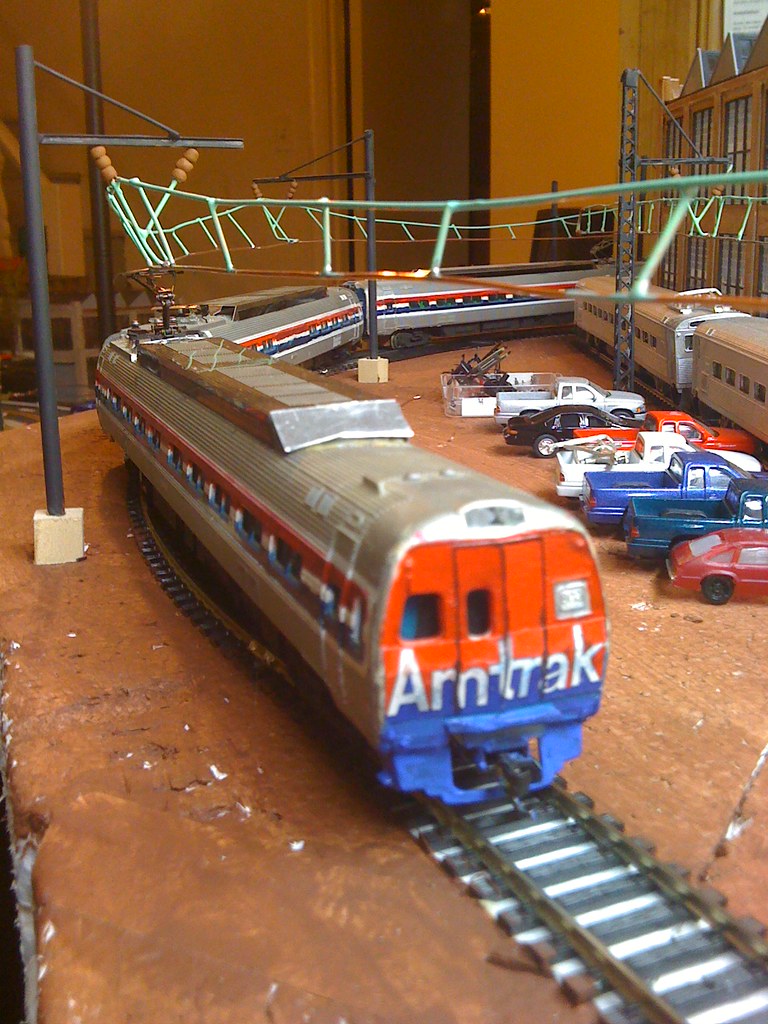
I have a pantograph project, and its making me insane.

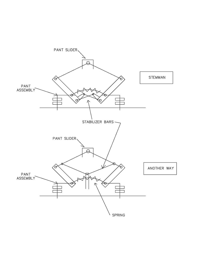
I'm build a stemman style pantograph, used on the Jersey Arrow MUs and many Metroliner cars. The arms weren't to hard, and i just figured out how to build the base of the pantographs accurately. However, I'm having problems with the equalizer bars.

Diamond shaped pantographs need two of these. they keep the arms folding in sequence. However, i can't seem to find a the right length for them, and when i think i do, the mountings for the equalizer bars tend to pull off, showing they are too tight.

does anyone have any experience with such a model?
  by ac0catenary
 
i tried doing that about 15 years ago.. And it didnt come out looking like the protoype. I used two of the old metro pants but took off the Faively top and built a stemman top. I had to add a stabilizer bar for each arm to it ended up looking like 2 pantographs fused together with the two bars. otherwise the pant would move back or forward according to the direction on travel. The set up worked well till it got caught up in the catenary on a derailment at highspeed and that was the end of that. I would suggest using a IHC pantagraph bottom from a GG-1 that has bars under the assembly. that will stop the rocking or fuse 2 high quality marklin pants together. Goodluck ,, For real nightmare try building a "protypical" orange Pant for a SEPTA or NJT AEM7/ALP44 ..HHP in Ho scale IMPOSSIBLE and no one makes them functional .. BTW installed that new Amtrak Big letter decal for GE metroliner cars check it out .. I gotta redo the striping for Phase2 Image
  by green_elite_cab
 
I'm starting to think that this require a bit more math than i thought.

I'm going to take some graph paper and sketch it all out to scale, and see what i get.


I think i might also try and install the hooks for the equalizer bars directly into the horizontal piece at the base of the arm, as opposed to soldering it to the outside. That way, the hooks won't pull off if i make an error in my equalizer bar length.

When i sketch it out, i should be able to figure out the right size.

In fact, i might just go ahead and pick up some Eye-bolts and make life easier.
  by ac0catenary
 
i suggest you set it up like this . Im going to have to build another one now for one the metroliners For diamond pants you need stabilizers for each side Image
  by green_elite_cab
 
ac0catenary wrote:i suggest you set it up like this . Im going to have to build another one now for one the metroliners For diamond pants you need stabilizers for each side
already had it like the upper photo. I just can't seem to get the equalizer bars to match up. That's the only thing holding me up.
  by cnj1524
 
stop ur all gonna hurt ur selves,Ok I will dig out the prints for arrow III(REBUILDS)will pass off to fellow modeler
and he will decide for production run

hope this helps
  by green_elite_cab
 
LOL! You have the drawings for an Arrow III? i need a copy of that!

I think i'll still go for it. I found an interesting article in a 1974 Model Railroader where a guy scratch builds pantographs for his MP54 MUs. His pan only uses one equalizer bar. I think that if you calibrate it the right way, it will work with just one.
For real nightmare try building a "protypical" orange Pant for a SEPTA or NJT AEM7/ALP44 ..HHP in Ho scale IMPOSSIBLE and no one makes them functional .
Impossible, you say? How so? I thought the ones on the acela (not the HHP-8) looked pretty good, and i have a broken one that i'm going to play with until it looks right.

I think alot of this just requires a knowledge of mechanical engineering i don't have. when it comes to things swiveling and turning about, it can always be made smaller.
  by ac0catenary
 
green_elite_cab wrote:
Impossible, you say? How so? I thought the ones on the acela (not the HHP-8) looked pretty good, and i have a broken one that i'm going to play with until it looks right.

I think alot of this just requires a knowledge of mechanical engineering i don't have. when it comes to things swiveling and turning about, it can always be made smaller.
The "Prototypical" Brecknell orange pantograpghs for AEM7 and HHP does not have a visible stabilizer bar. The stabilizer bar/chain is located inside the pantograph arm. This would be hard to reproduce in "O" Scale and in my opinion impossible for a working/conductive pant in HO scale. The Bachmann Acela pants try to mimic this but no cigar. In my opinion they "suck" from vast experience with them and they do not perform at any level and I have at least 5 broken ones
1. They are flimsy
2. Do not conduct electricity consistantly. no electric conductive paint that is available on Most European manufactured pants
3. The pant slider is to sharp at the edges(non forgiving) and will catch on any type of wire especially if the pant is setup back wards

Atlas pants are better but don't conduct electricity consistently either ,but with some good soldering you can place jumper wires between the joints.
Bachmann New HHP pant is better than the Acela but still doesn't conduct consistently with Jumpers it performs OK

Some of these short comings might not matter to "most" but to me They are a big deal. If they don't work they might as well be plastic. Pantographs are made to conduct electricity just like trolley poles
  by ApproachMedium
 
The pans that came on my Marklin and Roco DB101 engines are very nice and look like they would work very well. They are all metal. Maybe give them some inspection and see if you can work a design off of that?
  by ac0catenary
 
ApproachMedium wrote:The pans that came on my Marklin and Roco DB101 engines are very nice and look like they would work very well. They are all metal. Maybe give them some inspection and see if you can work a design off of that?
Thats all I use are Marklin, Sommerfedt, Roco and Lima Pantographs They are the Best!
  by green_elite_cab
 
ac0catenary wrote:
green_elite_cab wrote:
Impossible, you say? How so? I thought the ones on the acela (not the HHP-8) looked pretty good, and i have a broken one that i'm going to play with until it looks right.

I think alot of this just requires a knowledge of mechanical engineering i don't have. when it comes to things swiveling and turning about, it can always be made smaller.
The "Prototypical" Brecknell orange pantograpghs for AEM7 and HHP does not have a visible stabilizer bar. The stabilizer bar/chain is located inside the pantograph arm. This would be hard to reproduce in "O" Scale and in my opinion impossible for a working/conductive pant in HO scale. The Bachmann Acela pants try to mimic this but no cigar.
Here is my idea. The current Acela pans are channel shaped on the bottom half, right? I think a REALLY simple fix would be to solder in a small spring into the channel, and just connect the other end of the spring to the place where the that wire stabilizer bar currently attaches ( might even be able to play with this so that it doesn't poke to far out.

The only trick would be finding a good spring, but you know they are out there somewhere. if mounting the spring in the lower arm isn't good, you can put the spring elsewhere and tie it off with a skinny string or fishing line, and then just keep this line within the channel, and once again tie it to the upper arm thingy.

You'd also need to make a new locking mechanism to hold the lower arm down, but you can just do what they've been doing for ages, just bend some stiff wire so that you squeeze the lower arm in and out, just like on the atlas pantographs. Problem solved.

You could probably also wire that part up to, now that i think about it, so get better conductivity.

Now, fixing the pantograph shoes so they glide better will have to be the next thing i worry about.
  by ac0catenary
 
green_elite_cab wrote:
ac0catenary wrote:
green_elite_cab wrote:
Here is my idea. The current Acela pans are channel shaped on the bottom half, right? I think a REALLY simple fix would be to solder in a small spring into the channel, and just connect the other end of the spring to the place where the that wire stabilizer bar currently attaches ( might even be able to play with this so that it doesn't poke to far out.

The only trick would be finding a good spring, but you know they are out there somewhere. if mounting the spring in the lower arm isn't good, you can put the spring elsewhere and tie it off with a skinny string or fishing line, and then just keep this line within the channel, and once again tie it to the upper arm thingy.

You'd also need to make a new locking mechanism to hold the lower arm down, but you can just do what they've been doing for ages, just bend some stiff wire so that you squeeze the lower arm in and out, just like on the atlas pantographs. Problem solved.

You could probably also wire that part up to, now that i think about it, so get better conductivity.

Now, fixing the pantograph shoes so they glide better will have to be the next thing i worry about.
Your ideas sound like good ones. NEw pantograph sliders are available on EuroLokshop.com You might have to modify them to fit.
  by green_elite_cab
 
I've DONE IT!

and this time, i've ACTUALLY done it, not just thought i had it.


I installed a stabilizer bar on the stemman pan i was building, much the same way you'd find in a GG1 pantograph and such.

The trick i found is to build things a little bigger, and use "bearings" instead of "links". Basically, i had some 1/32 brass wire, and brass tube with an inside diameter of 1/32, so that they fit in with each other. I bent to sections of 1/32nd wire into right angles, and soldered one end to the arm facing "up", and on the other arm, had it facing "down" roughly the same distance from the base pivots. Make sure these are fixed to the arm with good solid solder joints (otherwise, they will break off under the stress if the pantograph hits anything).

I then took some brass tube, soldered a section of brass strip to it, then cut the tube flush. I left the brass strip long (this is important later), as the strip makes up the "Stabilizer bar". I cut another section of tube about the same size as the section soldered to the brass strip.

The brass tubes make up the "bearings" that will slide onto the wire "pivots" that were installed on the pantograph arm. Slip these bearings on the pivots, with the bearing soldered to the brass strip located on the "upper" wire, with the stabilizer bar going "over" the pivot. Positioning is important for proper movement. Also, it is easier to work on the bottom of the pantograph so you don't have to work on the "inside" of the double arms.

Once you have everything loosely fitted, position the pantograph arms where they should be relative to each other (either by fully extending them, or folding them), and keep them steady. Lay the brass strip over the "bottom" (which is the top from below), and put the smallest drop of solder you can between the strip and the bearing. Let it cool and harden, then let your pantograph swing out, checking to see the arms raise symmetrically, and without being "loose".

If one arm raises higher than the other, just unsolder the brass strip and try again until they are even, then solder it again. this may take two or three tries.


You only need one stabilizer bar for the Stemman pantograph to be stable. I thought you would need to, but clearly, its not necessary. I suspect a second one might help make the pantograph a little more robust, and there is room for it, but i'll try that next time.


I'll post pictures as soon as my camera battery charges.
  by ApproachMedium
 
That should be fine because Im pretty sure the real ones only have a stabilizer bar on one side.
  by green_elite_cab
 
ApproachMedium wrote:That should be fine because Im pretty sure the real ones only have a stabilizer bar on one side.
i think you're mistaking the one up top for the functioning one in the base of the pantograph. I actually would have put that one in if i could find more 1/32 wire. don't know where it all went to!

Anyways, I'd like to find a new spring, because not only is this one huge (came for a GM 671 diesel blower seal), its also alittle stronger than i need it to be. I just found a website that sells springs more like the kinds we typically have in our models, so i'll see about them.


anyways, here it is.

Image

You can see how the stabilizer bar criss-crosses. you need this if you want your pantograph to stay "rigid" and not flop all over the place.

Image