Railroad Forums 

  • EMD Export Locomotives

  • Discussion of Electro-Motive locomotive products and technology, past and present. Official web site can be found here: http://www.emdiesels.com/.
Discussion of Electro-Motive locomotive products and technology, past and present. Official web site can be found here: http://www.emdiesels.com/.

Moderator: GOLDEN-ARM

 #1594185  by bogieman
 
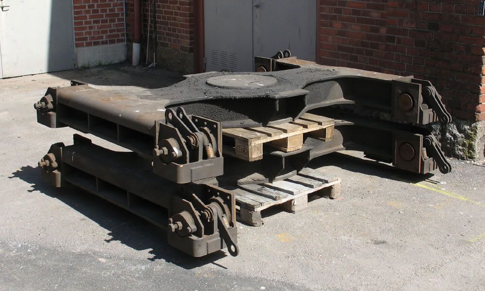
The part you have pictured is called the bolster and this one is part of the EMD GC bogie. Circled in red is the center bearing bowl; a mating circular part called the center bearing is welded to the bottom of the underframe of the locomotive which allows the bogie to swivel in curves while transferring the locomotive weight to the bolster. The yellow circled areas are the side bearings that mate with similar pads welded to the underframe - they have about 6mm clearance so they do not normally contact in service - they are there so if the body of the locomotive rolls they will contact and limit the roll. Between the bottom of the bolster and the bogie frame are coil springs that support the weight of the locomotive body. These springs deflect about 100mm under the locomotive weight to give a smooth ride.

Dave
 #1594312  by AllenHazen
 
GoranH--
(Bogieman is one of the posters to this forum who really does know what he is talking about.)
In answer to your question about the trucks detaching from the locomotive body: it does sometimes happen.
http://www.northeast.railfan.net/images/prr9628.jpg
At least some early (pre-WW II) diesels had heavy chains connecting the truck to the body to keep them from getting TOO far apart in the case of a wreck.
 #1594332  by bogieman
 
I should have mentioned that all EMD bogies have interlocks between the bogie and underframe to prevent the bogie from detaching in a derailment. IIRC, on the GC bogie there are interlocks from the underframe to bolster and from the bolster to the bogie frame. On some bogies, the connection is directly from underframe to bogie frame. There are also rotation stops that prevent the bogie from rotating beyond a certain angle, usually around +/- 7 degrees from centered. The traction motor wheel-axle assembly also always has means that prevent it from detaching from the bogie frame. So a locomotive can be lifted by the jacking pads on the underframe and all parts of the bogie remain attached on all EMD locomotives and I suspect most if not all other builders as well.

Dave
 #1594577  by GoranH
 
Thank you guys for the explanation! So, the central pin of the locomotive frame is just lying to the central bowl of the bogie support bearing, like in the photo. In what way is it interlock from separation? I thought there was some big screw or nut. Is there any soft metal in the center bearing, such as bronze or brass, for less wear, as drawn in the picture (yellow)?
Image
Last edited by GoranH on Wed Mar 30, 2022 8:52 am, edited 2 times in total.
 #1595903  by bogieman
 
The interlock devices are separate from the center bearing, chains or hooks or links, if you look at the bogie carefully you should be able to identify those parts as they are all external to the bogie. What you have pictured in yellow are the center bearing wear liners; today they are made of nylon plastic with molybdenum added to reduce friction. Years ago they were brass or steel. There is oil added and seals to keep out dirt.

Dave