• GE Builders photo source?

  • Discussion of General Electric locomotive technology. Current official information can be found here: www.getransportation.com.
Discussion of General Electric locomotive technology. Current official information can be found here: www.getransportation.com.

Moderators: MEC407, AMTK84

  by scottychaos
 
Does anyone know a source for GE builder's photos?
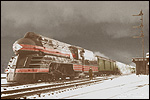
im specifically looking for the builders photo for this loco, built in 1949:

http://img344.imageshack.us/img344/7116/diesel027zs.jpg

I know a builders photo exists, because I just saw it! :P
The photo was published in the November, 1974 issue of Railroad Model Craftsman..I just found the issue at a local used bookstore..but it was in a bound volume of the entire year..
$30 for the whole bound volume of all of 1974.
I didnt want to pay $30 for just the one photo! ;)
(besides, the magazine version has heavy half-tone dots, lower quality)
I would like to find a crisp copy..

anyone have any ideas?
thanks,
Scot

  by Phil Hom
 
I use to write to Erie PA to get photos. But since they are the number one builder, you now get a form letter telling why they can't.

Maybe the GE museum in Erie has a friendlier staff.

For EMD photos, there's e-bay from a former EMD employee.

  by PortoAmboim
 
What's the story on that loco? It looks like an interesting little unit. Gauge? Weight? Operator?

  by scottychaos
 
PortoAmboim wrote:What's the story on that loco? It looks like an interesting little unit. Gauge? Weight? Operator?
Gauge?
2-foot! :)

Weight?
23ton

Operator?
Maine Narrow Gauge Museum, Portland, Maine.

here is everything I know about the three engines:

http://gold.mylargescale.com/Scottychao ... esel1.html

I have been asked to write an article about them for "Maine Two Foot Quarterly" magazine.
thats why I would like to find a photo of one "as built".
the wide walkways and handrails currently on #1 and #2 arent original.
they were added by Edaville.

thanks,
Scot

  by PortoAmboim
 
Thanks for that Scot. GE sure went to a lot of trouble to make them so narrow. The traction motors must be tiny!

We had 12 similarly-styled (but obviously a lot bigger) 3'6" gauge GEs assembled in Australia with an A1A+A1A wheel arrangement.

They weighed 134,394 pounds and were powered by the Cooper-Bessemer FWL-6T (rated at 640 horsepower for traction).

  by Wdobner
 
PortoAmboim wrote:Thanks for that Scot. GE sure went to a lot of trouble to make them so narrow. The traction motors must be tiny!
I was wondering if the reason for the trucks to be so long was that the traction motors fit into that space at the end of the truck space. I'd guess that the motor would occupy the entire space, from one side to another and then be geared to the axle at one or both end(s).

  by PortoAmboim
 
Wdobner wrote:I was wondering if the reason for the trucks to be so long was that the traction motors fit into that space at the end of the truck space. I'd guess that the motor would occupy the entire space, from one side to another and then be geared to the axle at one or both end(s).
Isn't that what GE did with the 2'0" gauge South African UM6B locos?

As you noted, looking at the photos on http://gold.mylargescale.com/Scottychao ... esel1.html you can't help but wonder what's inside the outer ends of the truck frames, and conclude it's probably traction motors.

Perhaps GE's 1949 design for using an electric transmission on the 2'0" gauge was the basis for the 1973 UM6B.

  by fcollingwood
 
PortoAmboim wrote:
Wdobner wrote:I was wondering if the reason for the trucks to be so long was that the traction motors fit into that space at the end of the truck space. I'd guess that the motor would occupy the entire space, from one side to another and then be geared to the axle at one or both end(s).
Isn't that what GE did with the 2'0" gauge South African UM6B locos?

As you noted, looking at the photos on http://gold.mylargescale.com/Scottychao ... esel1.html you can't help but wonder what's inside the outer ends of the truck frames, and conclude it's probably traction motors.

Perhaps GE's 1949 design for using an electric transmission on the 2'0" gauge was the basis for the 1973 UM6B.
The SAR Class 91 UM6B motors are between the axles. As the motors are wider than the bogies, the bogies arch up over the motors, as can be seen in the photos on this page

  by Allen Hazen
 
From the photos of the UM6, it may have one motor per truck. (unless the second motor protrudes only on the other side?) The Maine critter has four: builder's plate information on it includes "4GHM844", meaning 4 motors of type HM844. Anybody know what sort of motor the South African unit has?[/u]

  by fcollingwood
 
No, the Class 91 has two motors per bogie, back to back, so yes the motor for one axle protrudes out one side, the motor for the other axle out the other side.

  by Allen Hazen
 
Thanks, fcollingwood! I think I can visualize the configuration. How to use a motor that is two ... wide? long? anyway, too big along the axis the armature is parallel to to fit between the wheels of the locomotive. Do you happen to know the motor model number?

  by Allen Hazen
 
Mike Roque:
Thank you! That's beautiful! A dimensioned drawing-- time for someone who models main narrow-guage and likes alternative history to start planning on what a 1970's-era diesel color scheme for the Sandy River would look like (Grin!).
I'd managed to find another source for the traction motor model number ("Jane's World Railways," 1986-1987 edition, South African Railways entry, has a table of diesel classes with some data), but your diagram confirms that the Class 91 UM6B has model 778 traction motors-- thanks for answering my question as will as for the drawing! ... ... From the photos, though, it looks as if the traction motor is mounted a bit higher in the truck than the diagram suggests.

  by Allen Hazen
 
Cancel the final comment, therre: looking again, I realize that I had managed, somehow, to misremember totally the truck configuration I had been looking at in photos yesterday! As far as I can see looking at the photos again
http://www.sa-transport.co.za/train_mod ... co/91.html
the diagram is right.