Railroad Forums 

  • 3640 Restoration Project

  • Discussion Related to the Reading Company 1833-1976 and it's predecessors Philadelphia and Reading Rail Road and then the Philadelphia and Reading Railway.
Discussion Related to the Reading Company 1833-1976 and it's predecessors Philadelphia and Reading Rail Road and then the Philadelphia and Reading Railway.

Moderator: Franklin Gowen

 #531026  by RDG Diesel
 
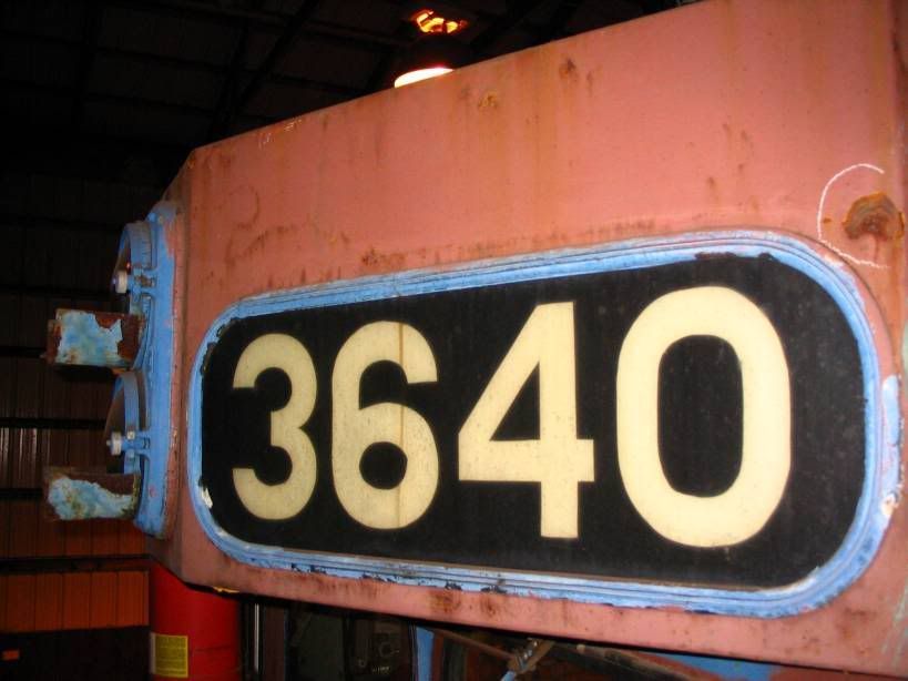
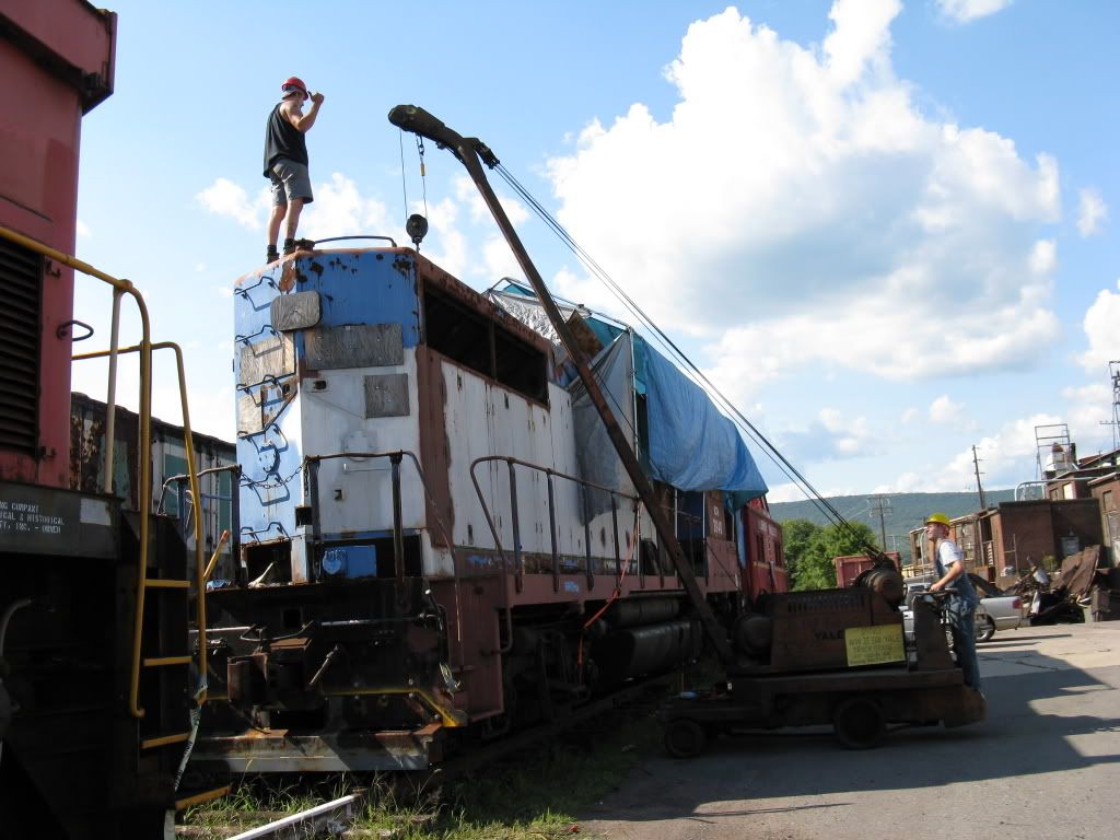
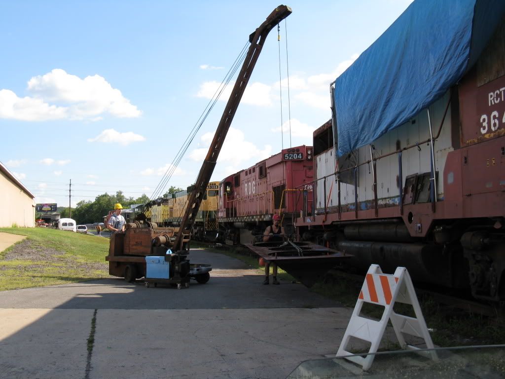
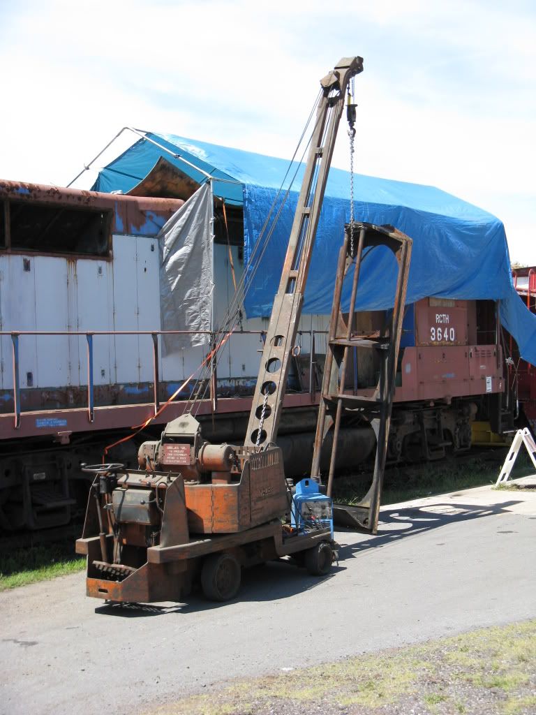
Over the last 2 years the RCT&HS has been restoring EX RDG GP-35 #3640 it was built in 1964 by EMD

Image

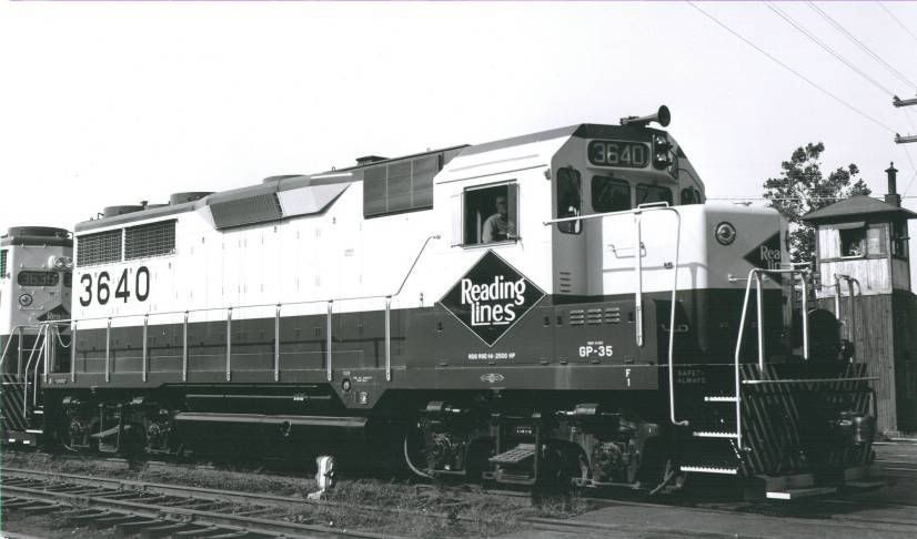
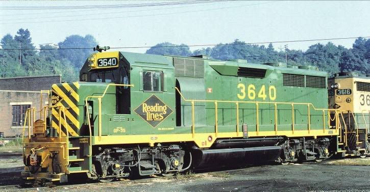
It was later rebuilt by the Reading Company in 1974. It also had the distinction of being the only RDG GP-35 to receive the Reading's final "all green" scheme

Image

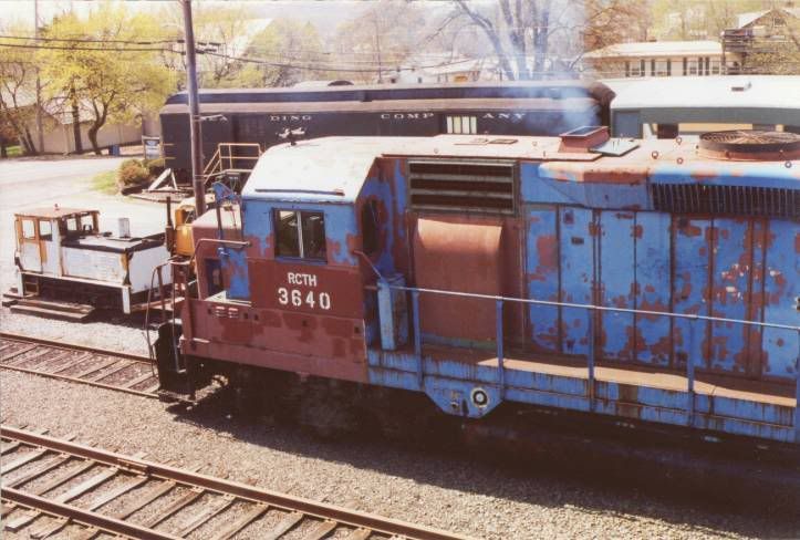
3640 was acquired by the RCT&HS in 1994 and was returned to service in 2002.

Image

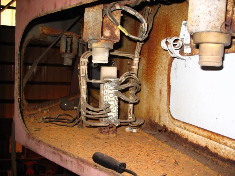
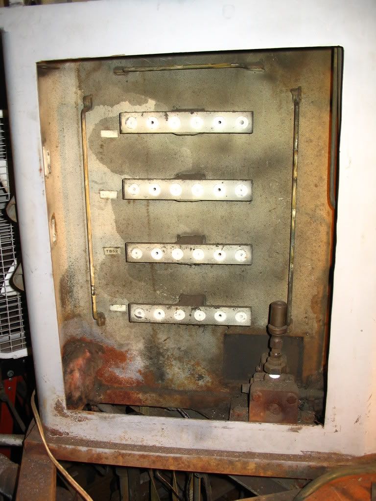
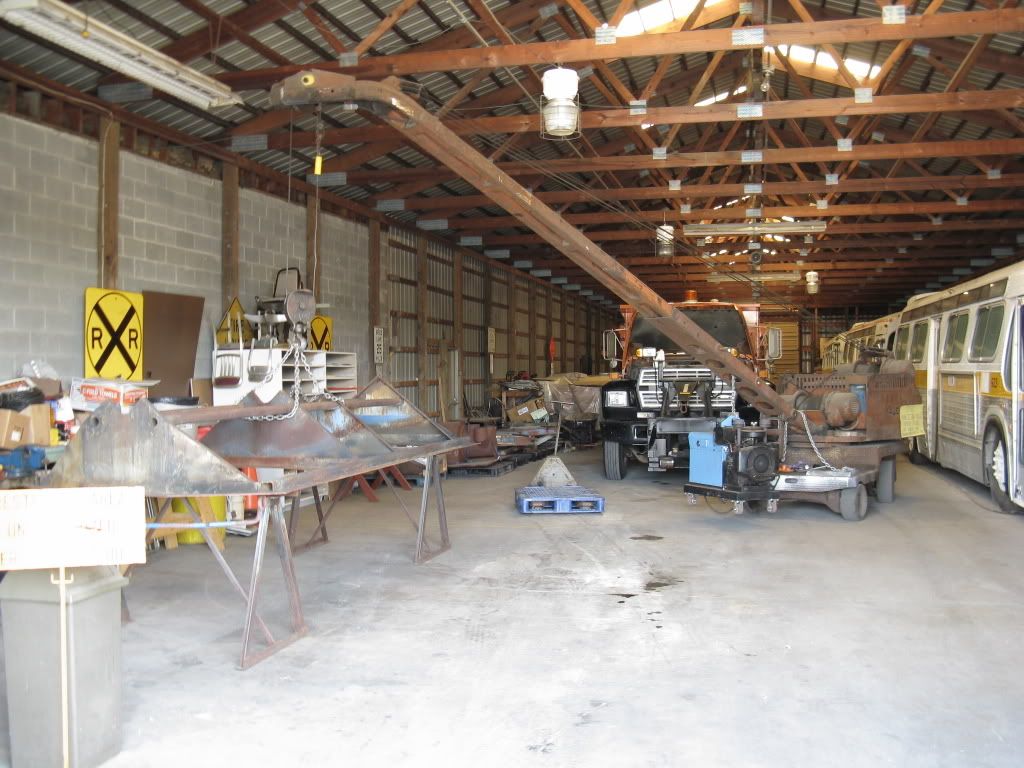
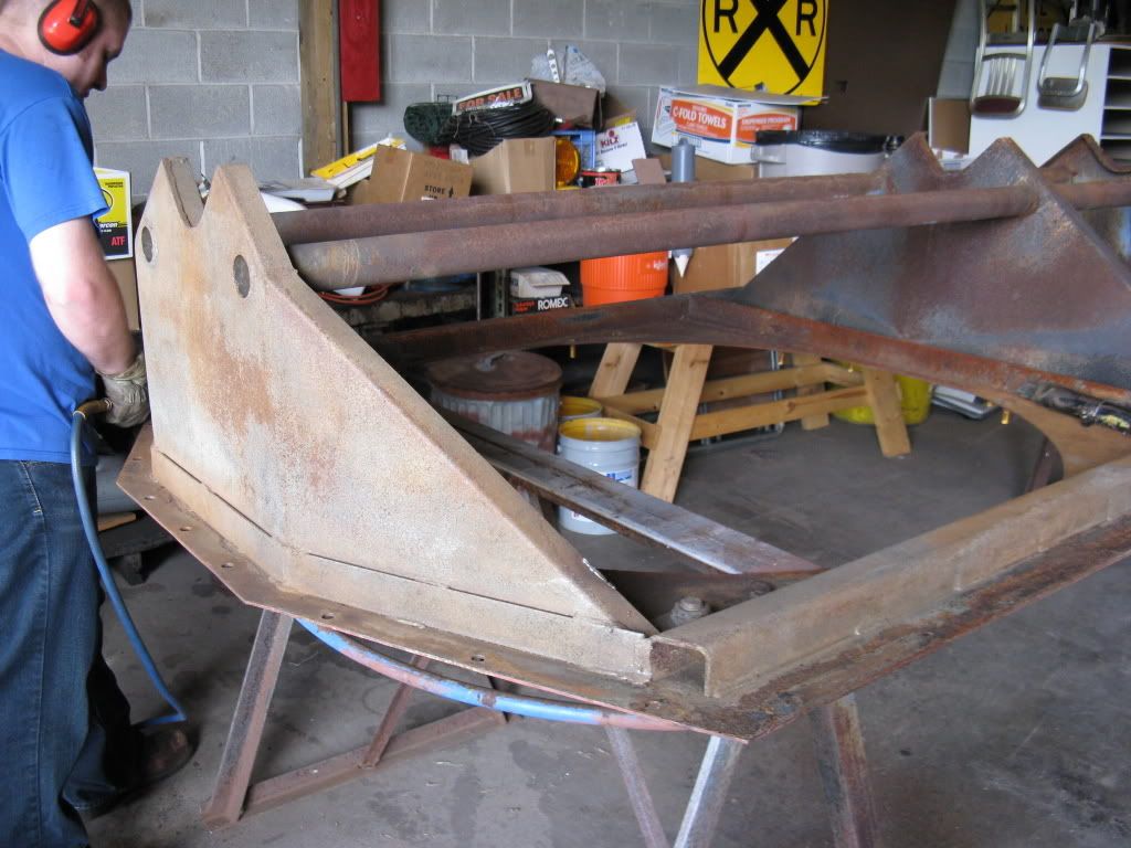
One of the projects we did to 3640 was to completely rebuilt the Battery boxes this series of photos shows the restoration process.

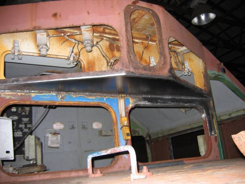
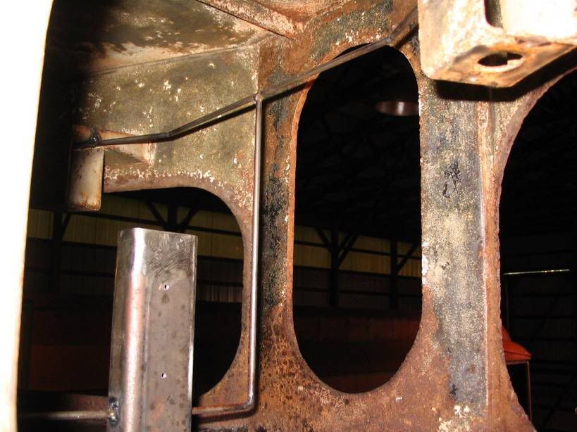
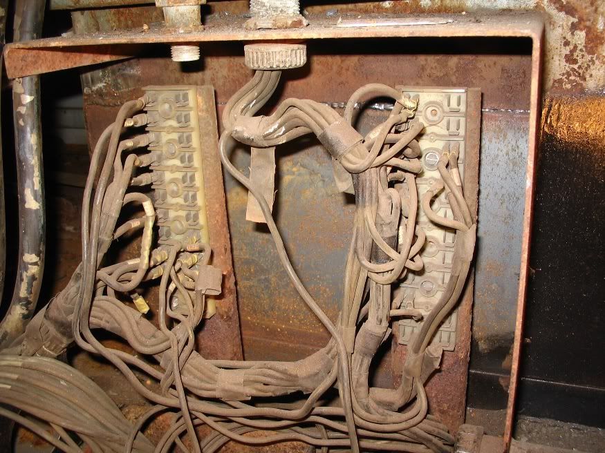
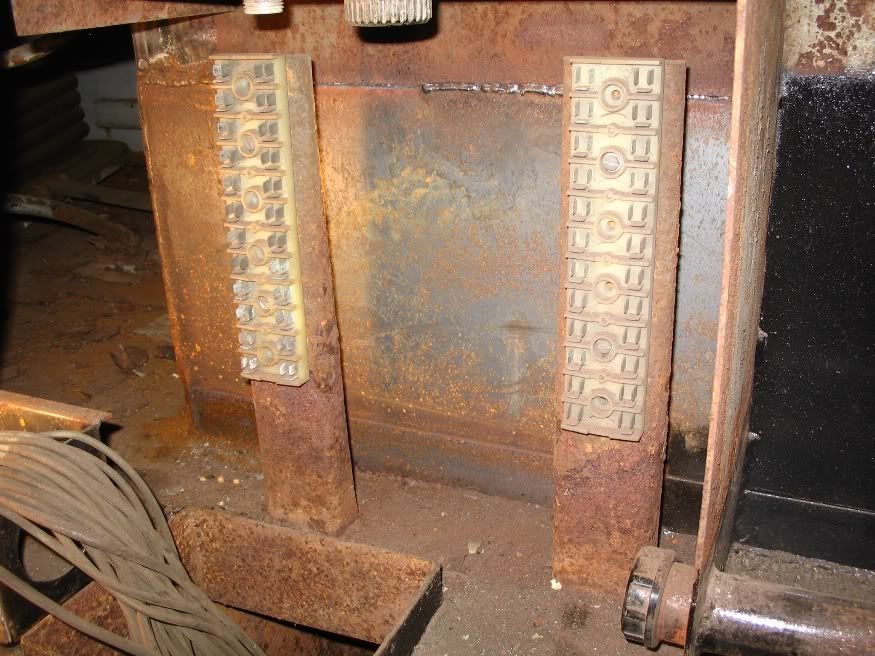
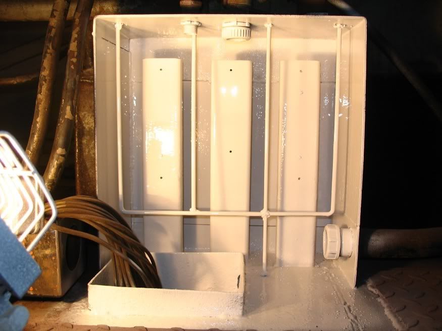
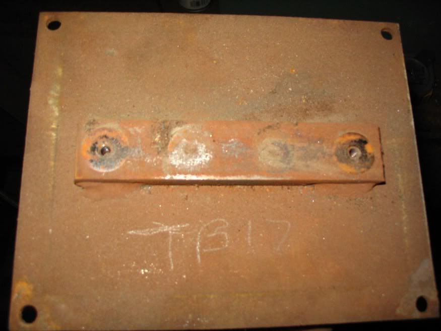
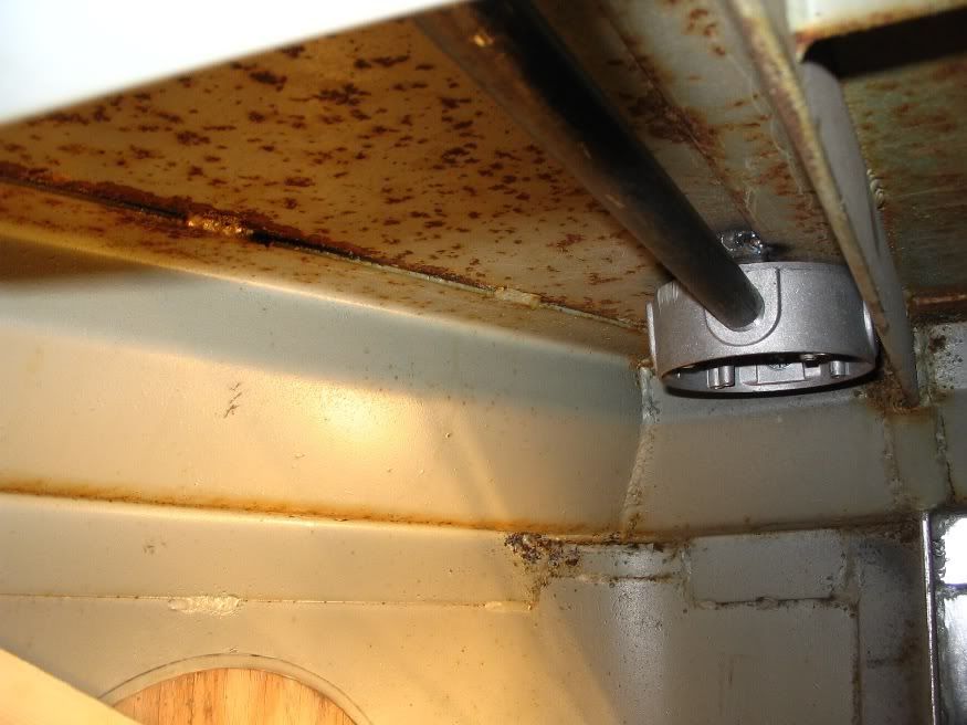
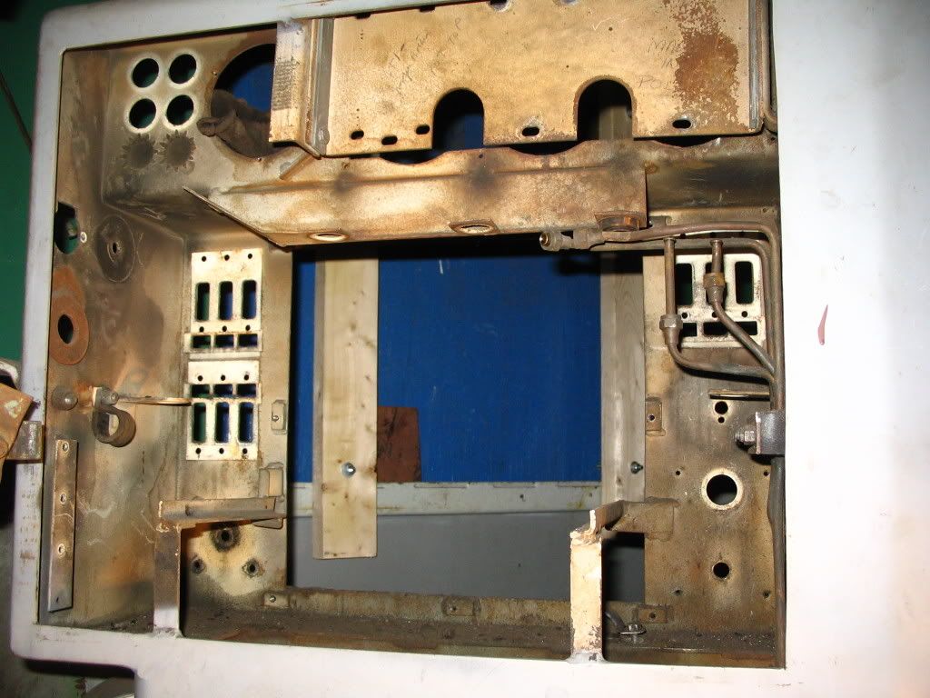
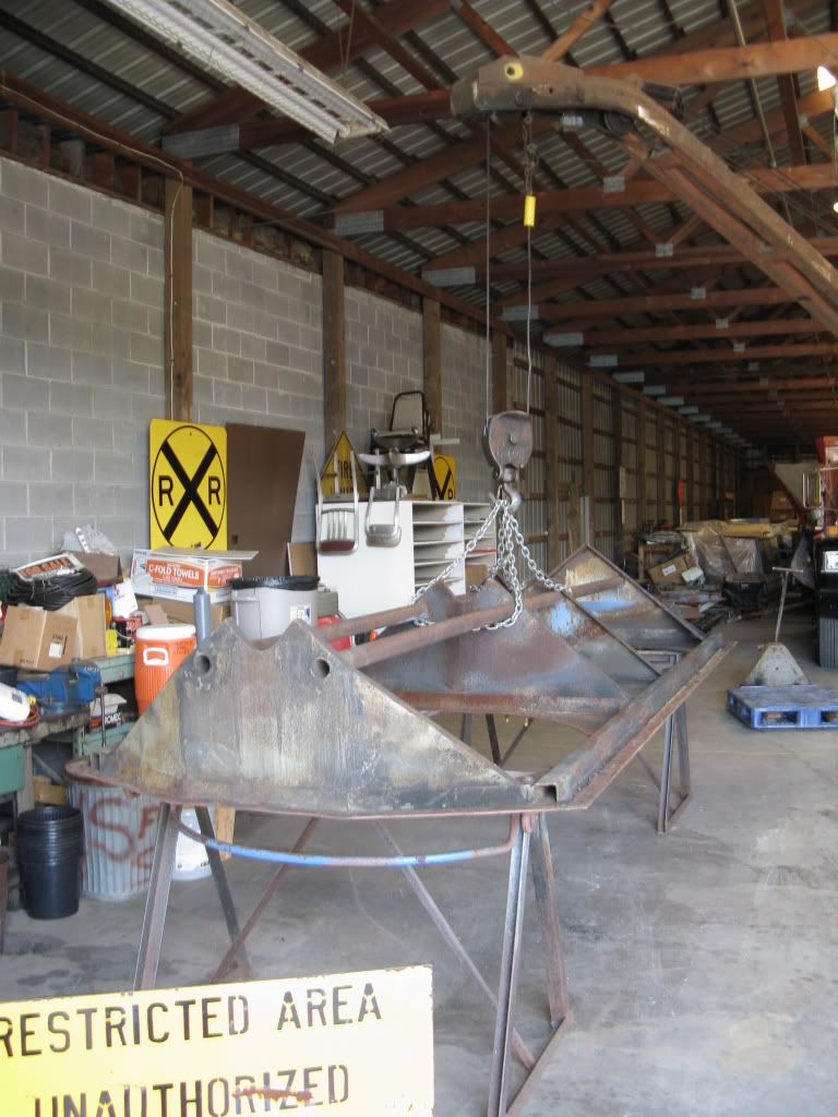
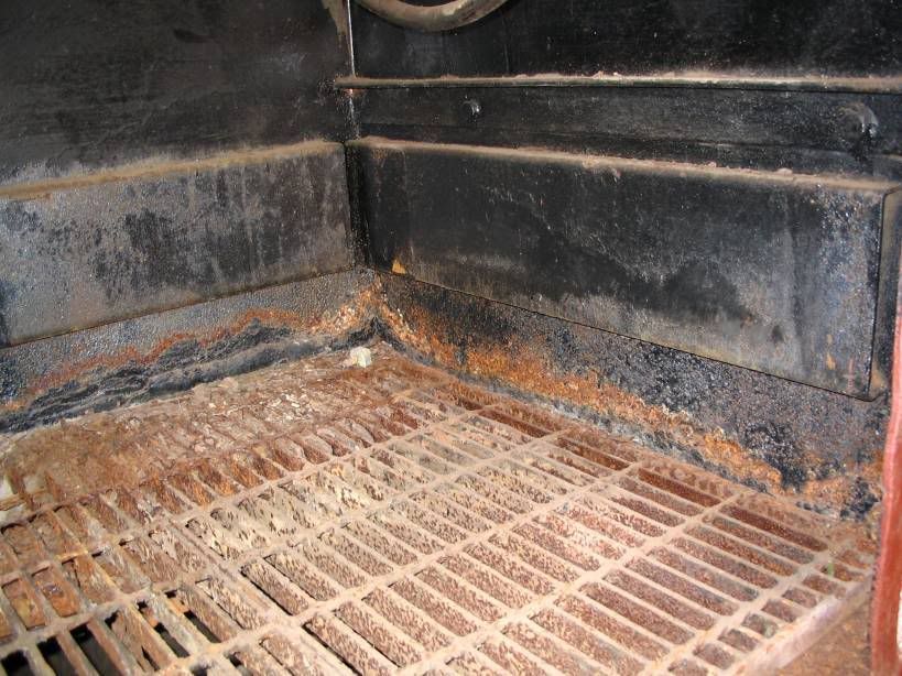
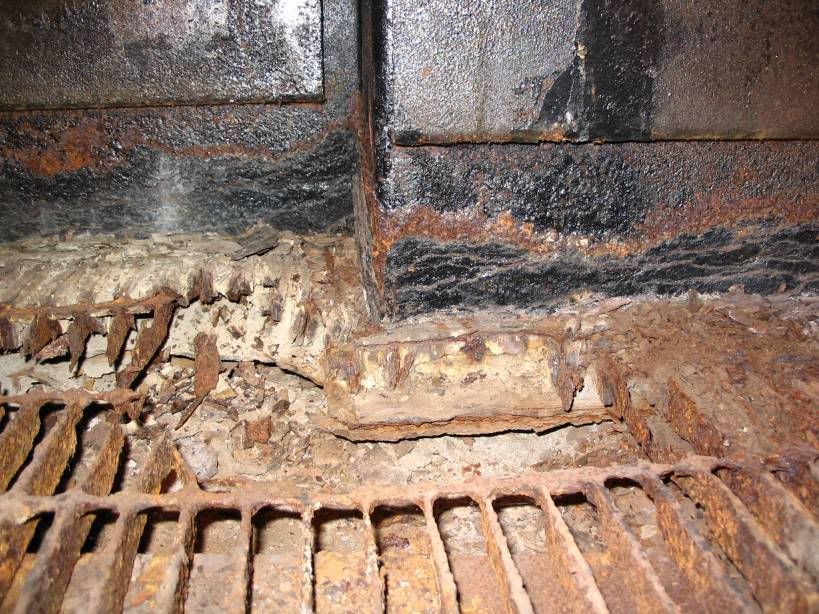
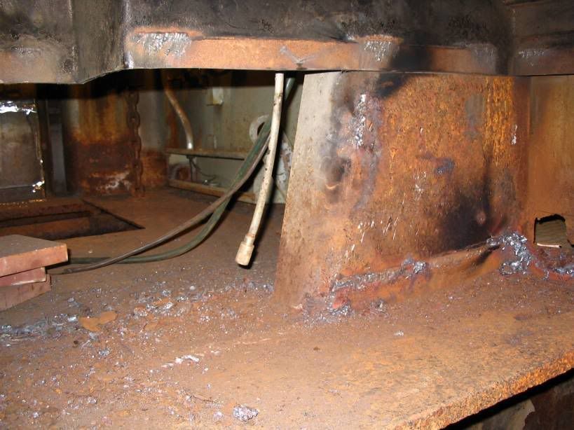
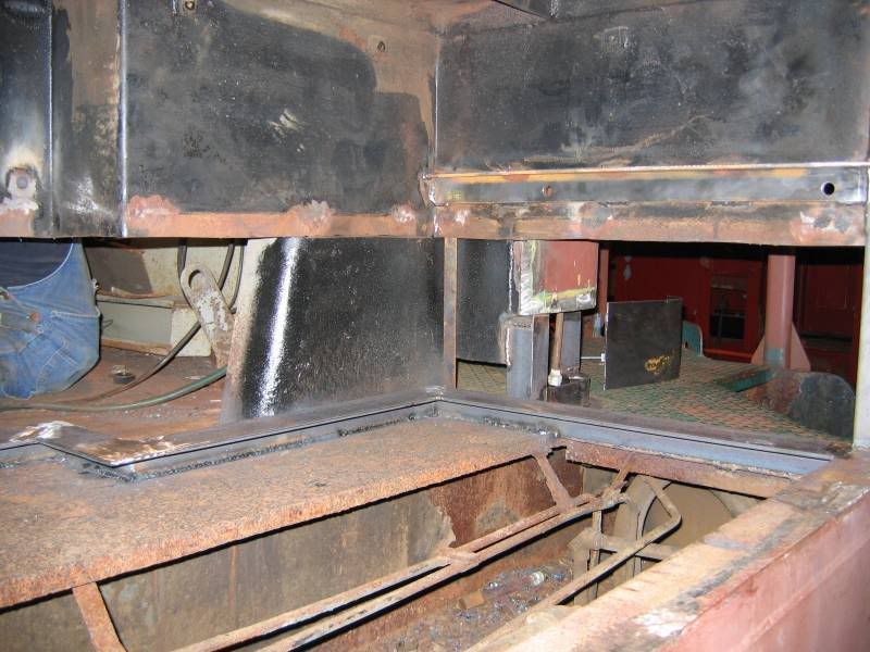
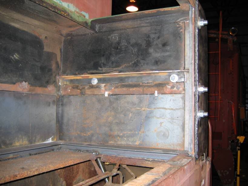
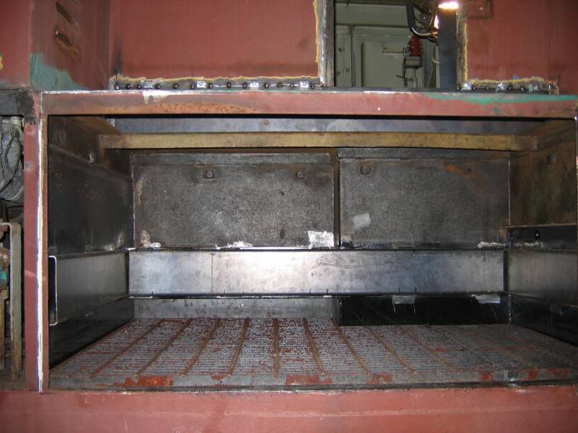
This is the Front corner of the Battery box before any work was done to it

Image

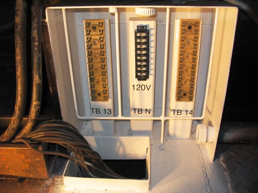
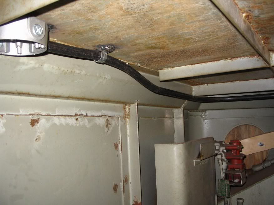
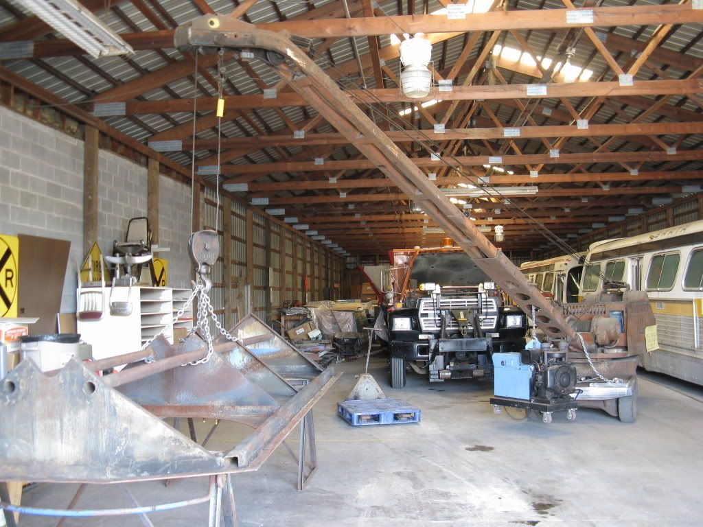
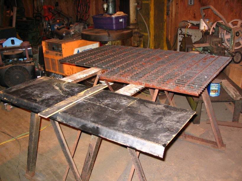
After the grate was removed

Image

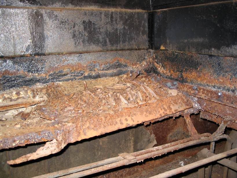
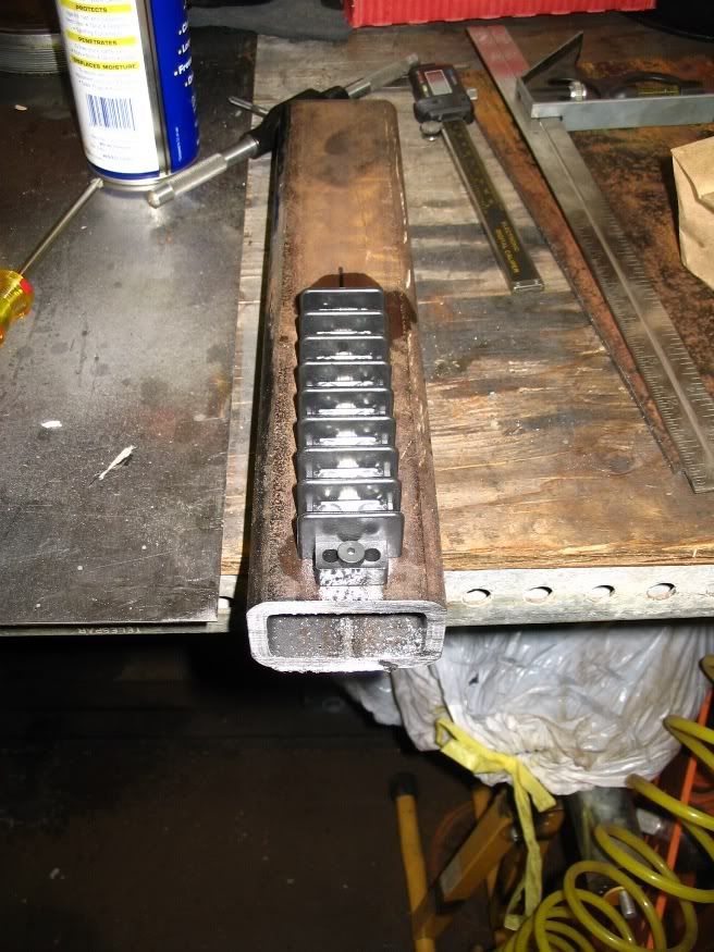
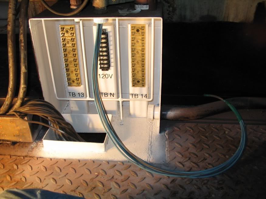
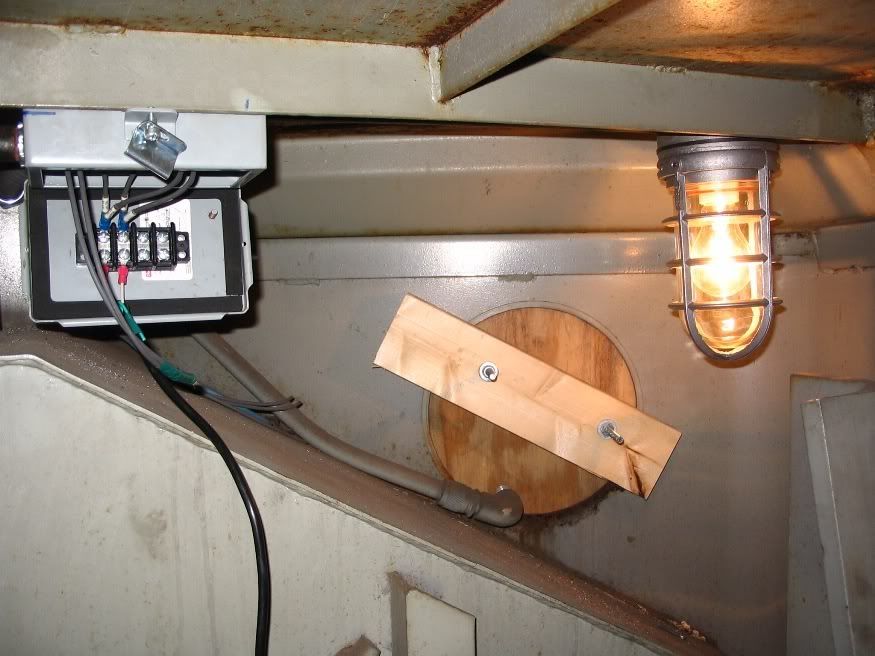
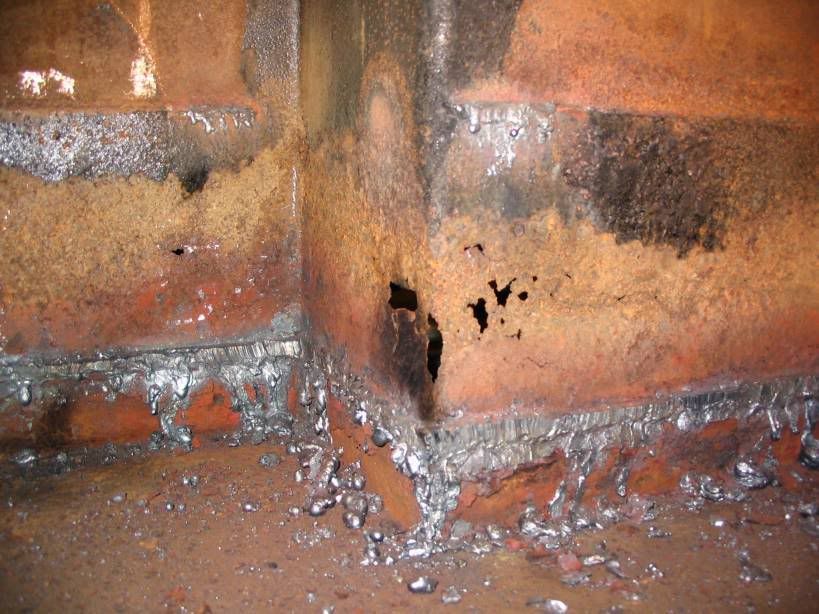
And after the spacers were torched out

Image

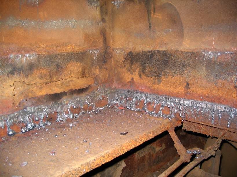
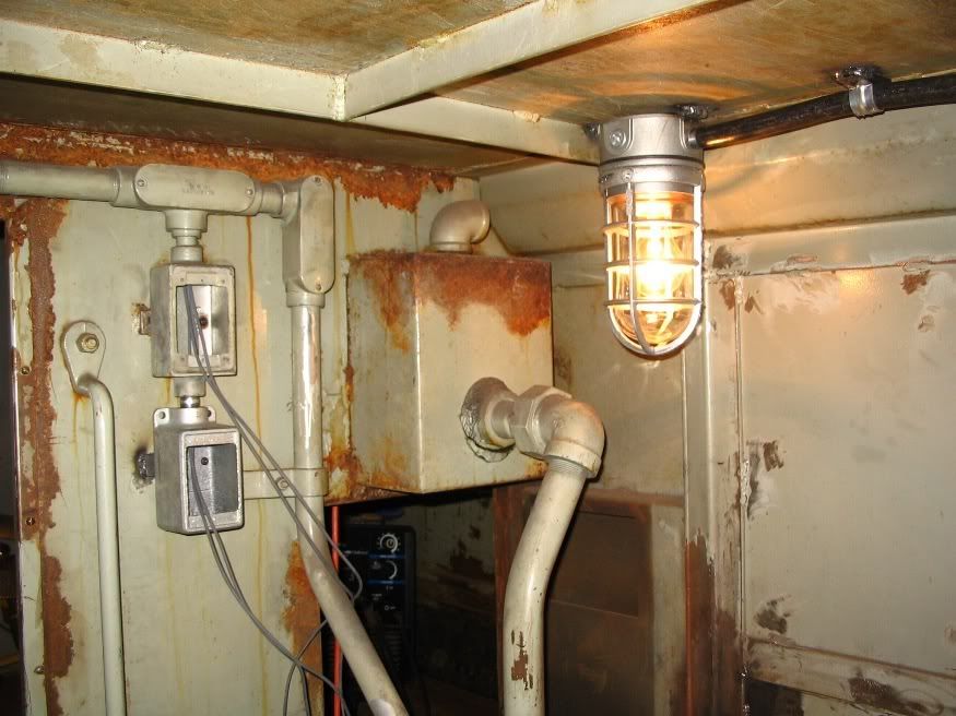
Same view again with more metal removed

Image

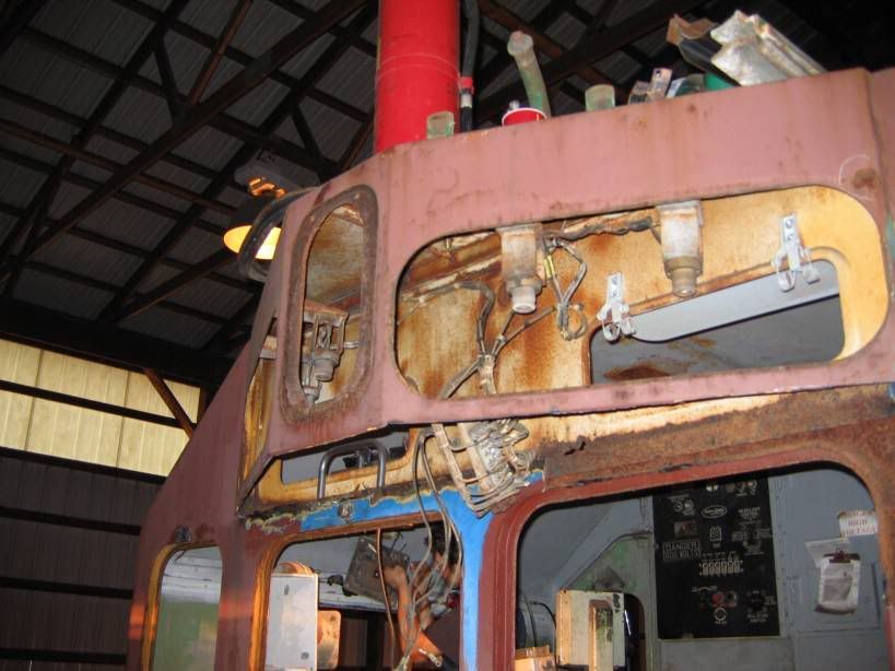
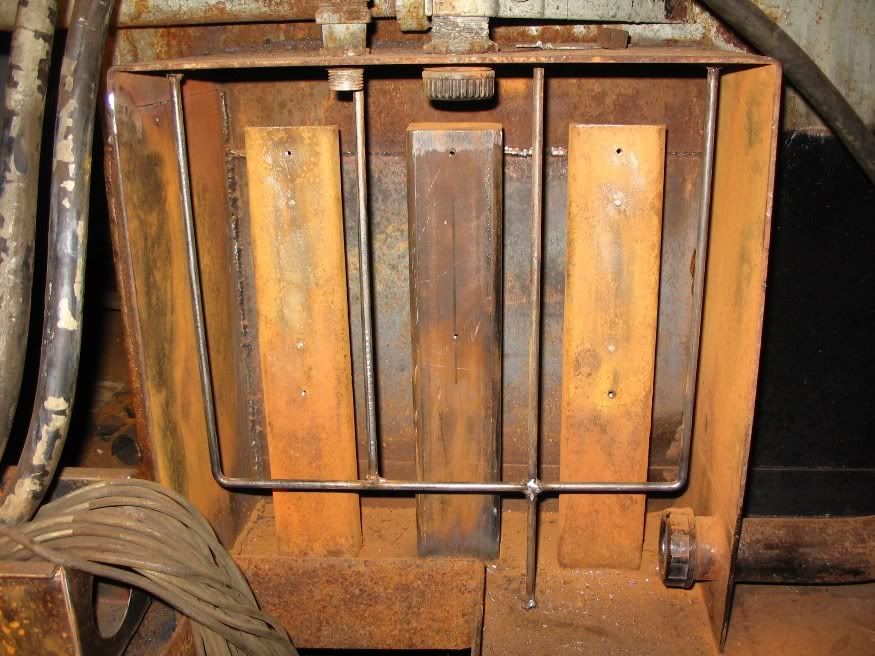
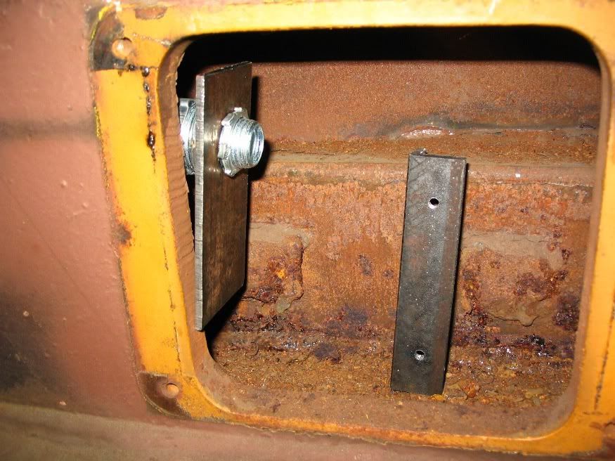
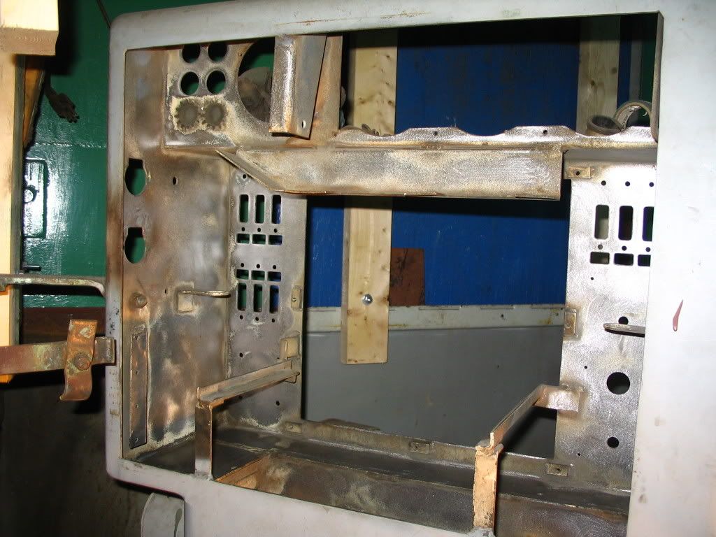
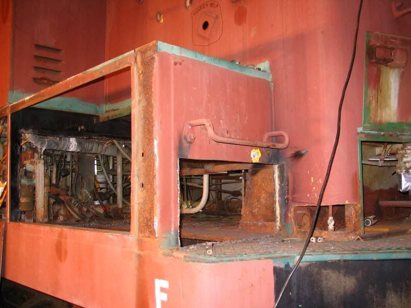
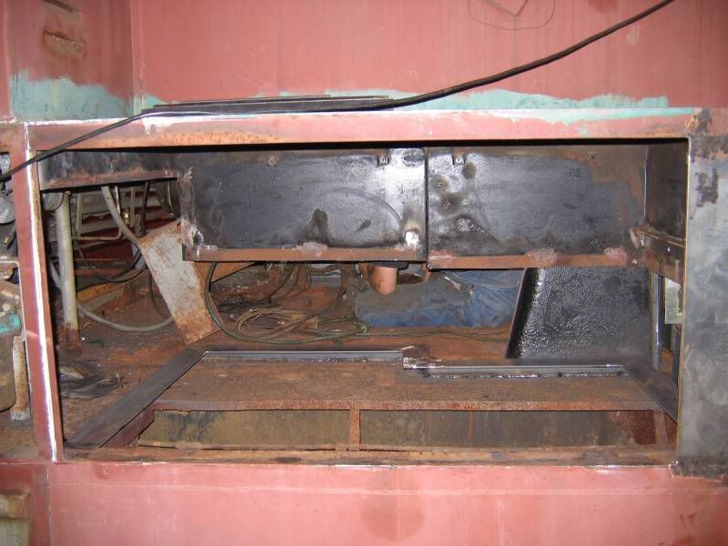
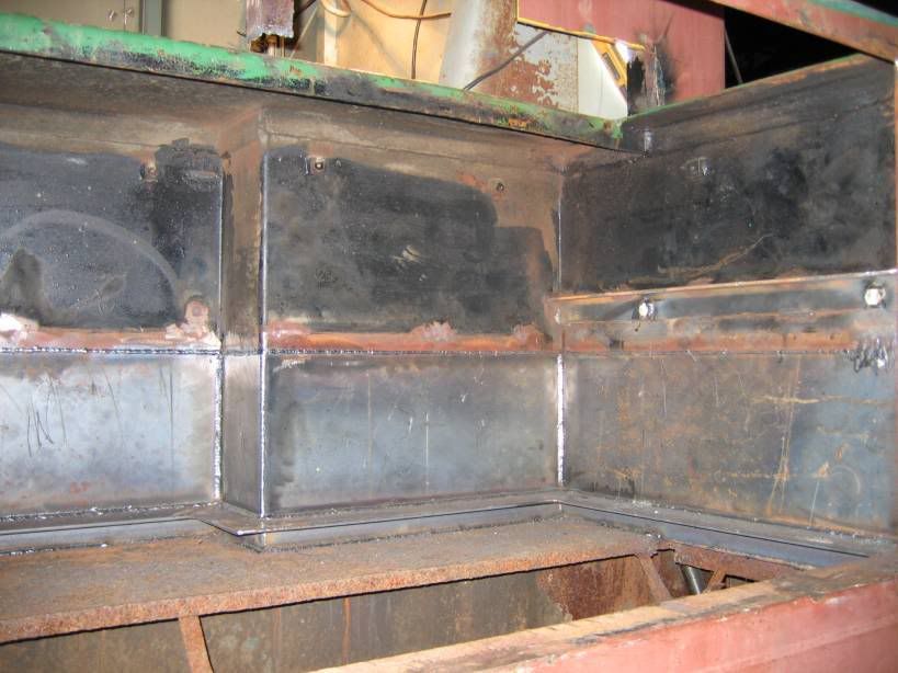
A view showing the middle before any work was done

Image

After the grate and spacer were removed

Image

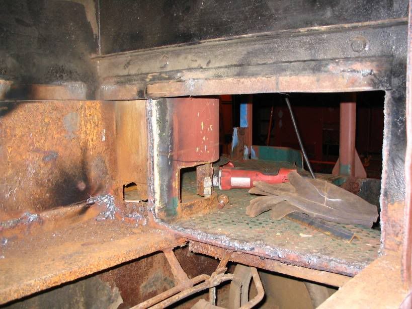
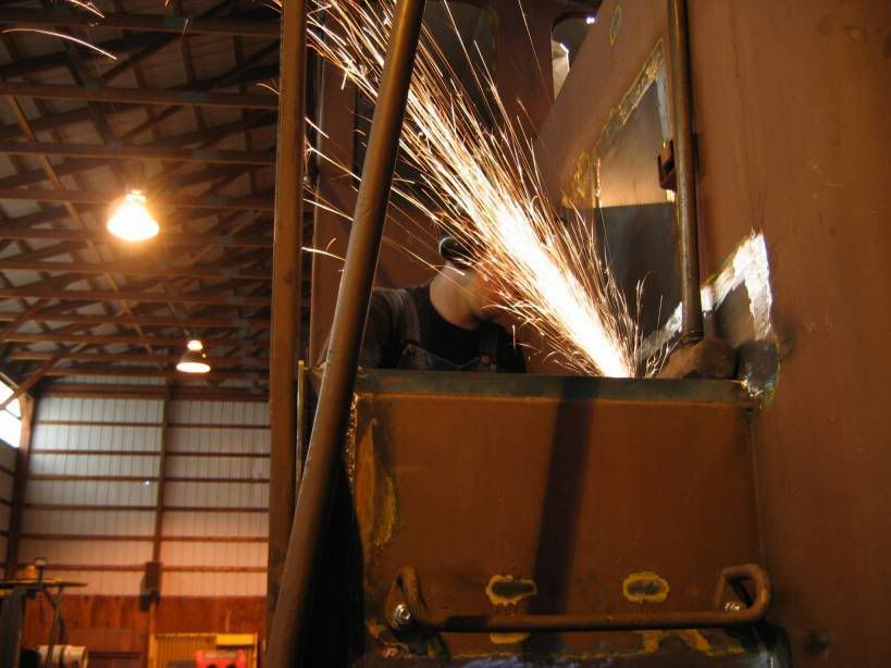
Torching out the bad metal

Image

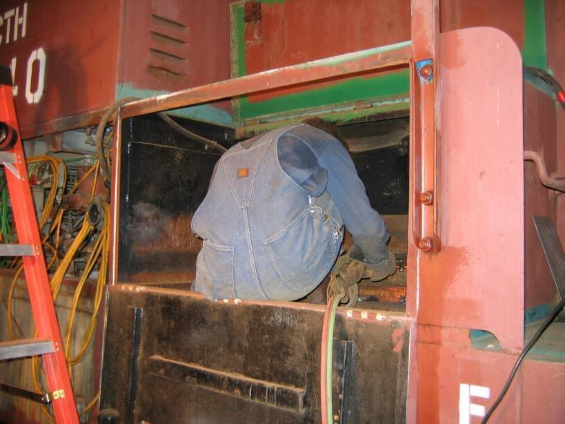
Starting to get there

Image

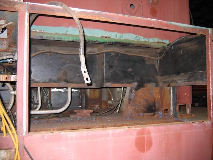
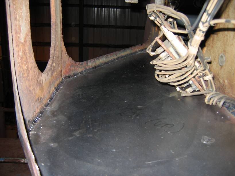
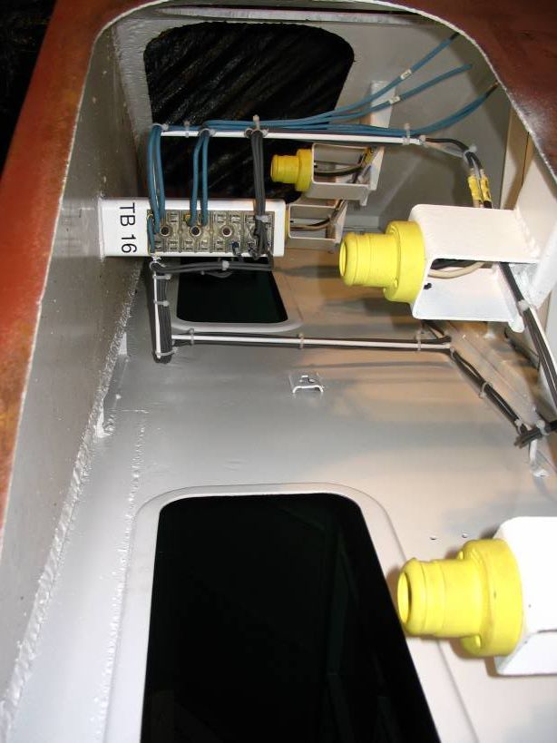
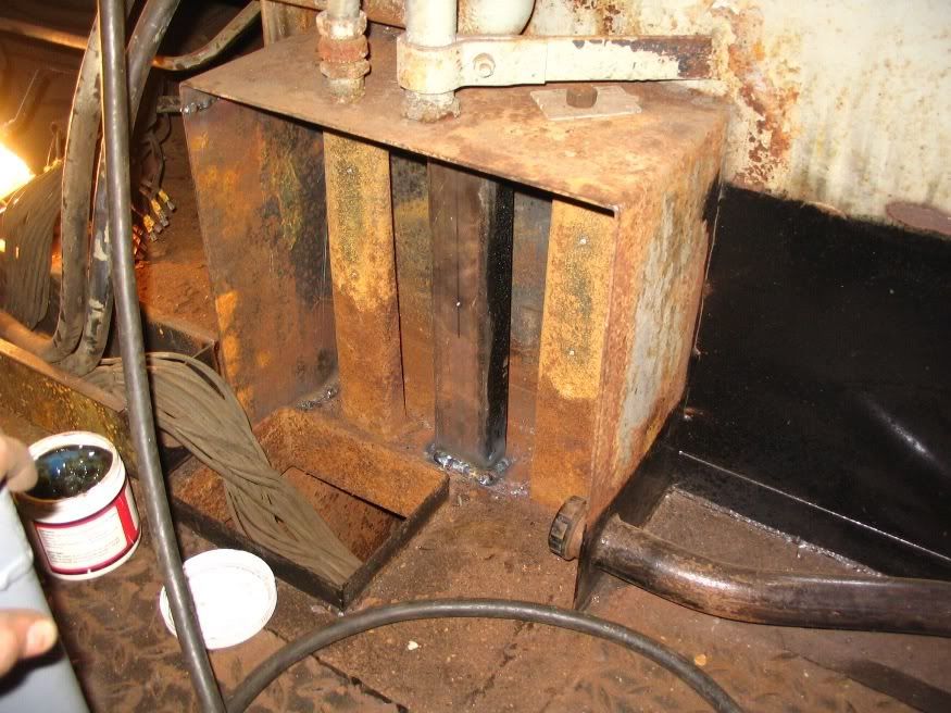
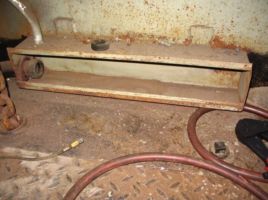
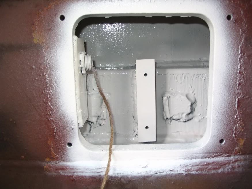
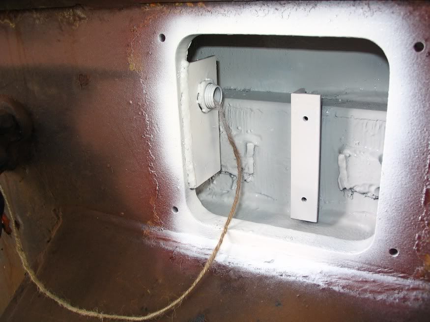
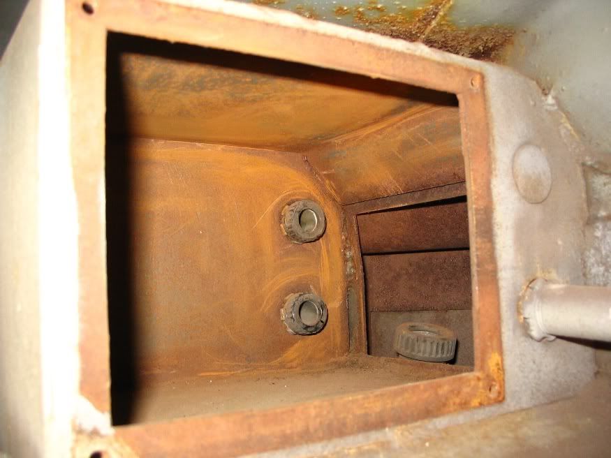
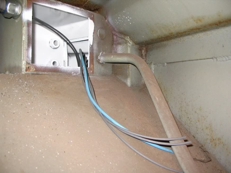
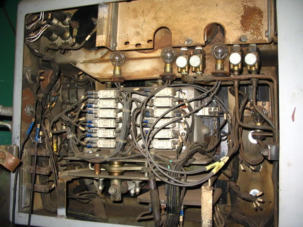
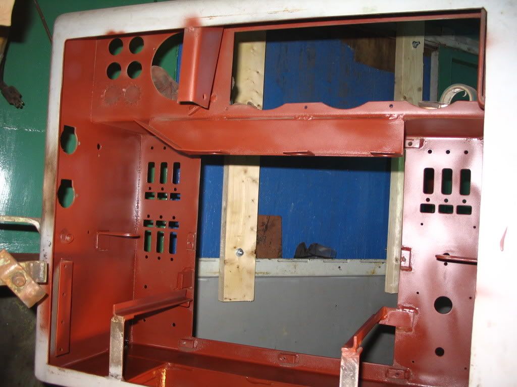
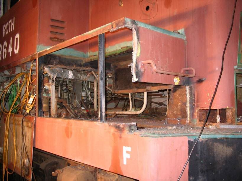
A view looking at the rear of the box after everything is stripped out

Image

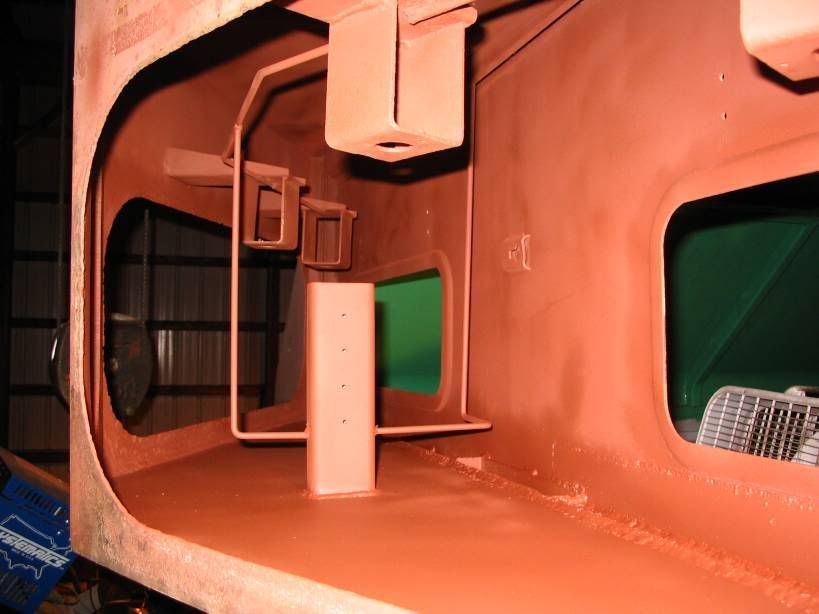
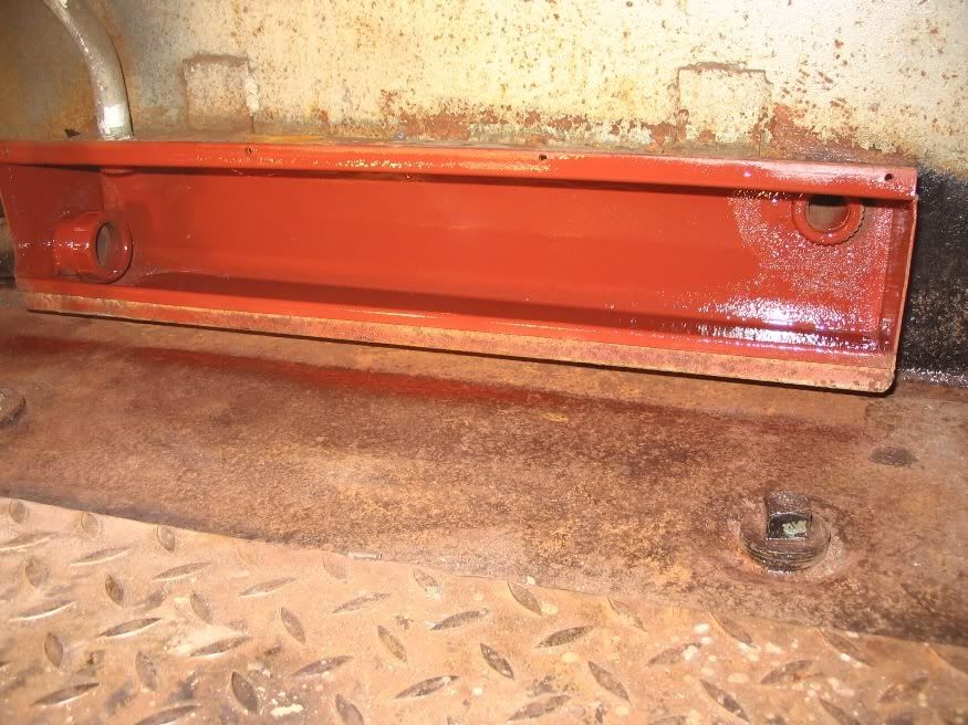
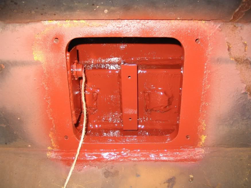
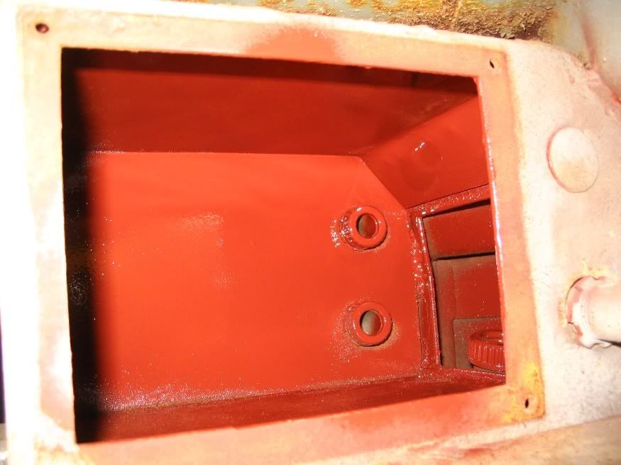
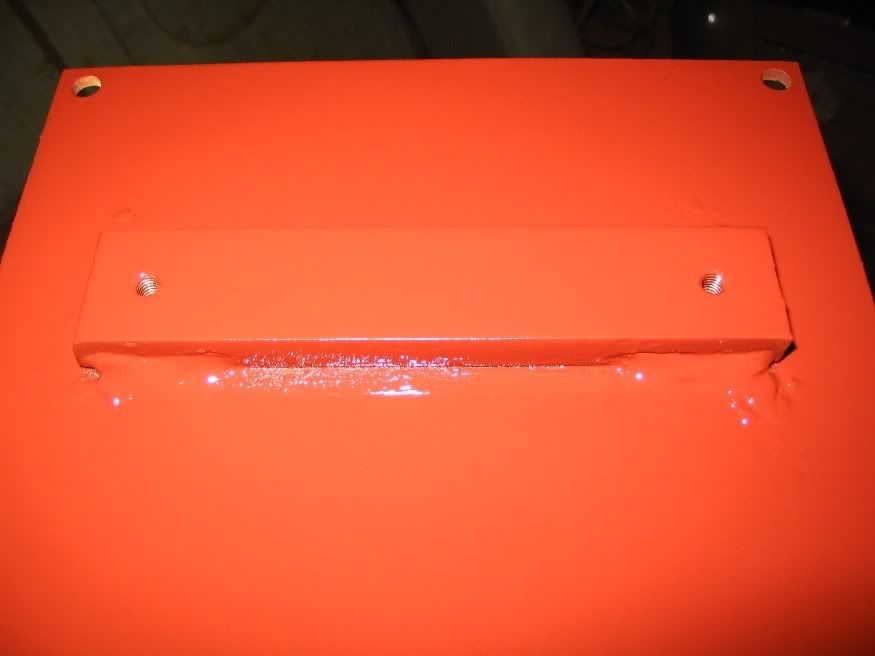
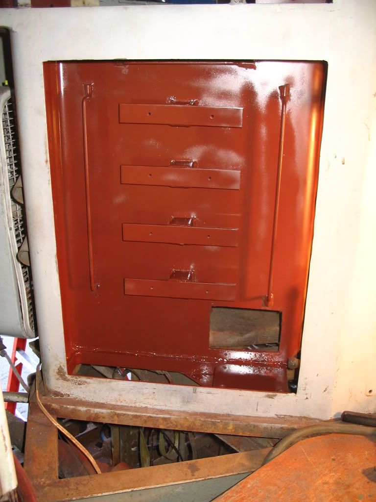
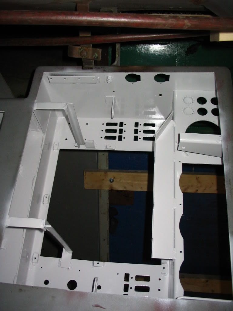
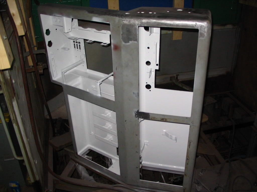
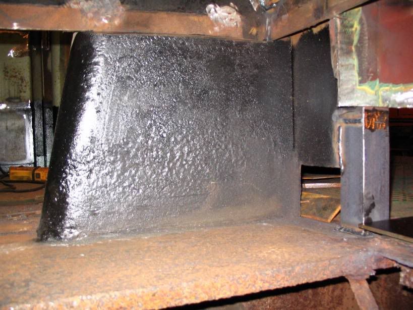
After everything was needle scaled it got painted with rust inhibitor

Image

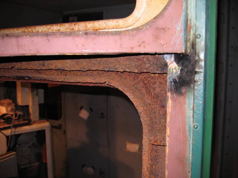
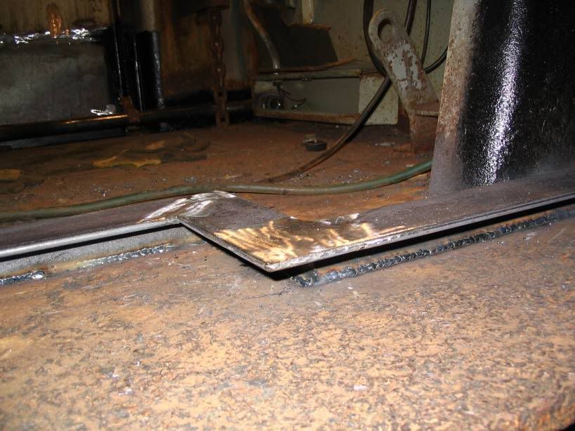
The front corner was a little bent up

Image

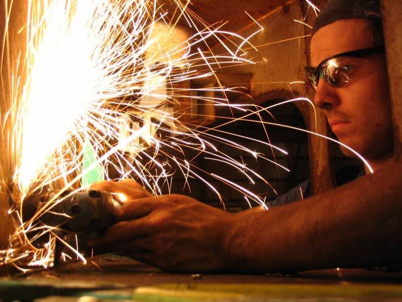
So it was all cut out

Image

And replaced

Image

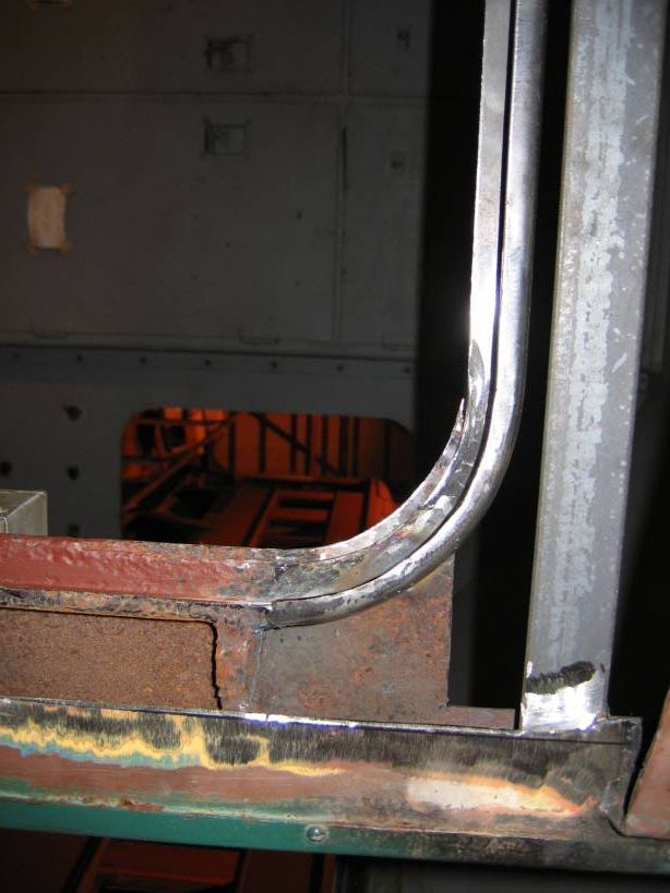
The new trim piece was then welded in place
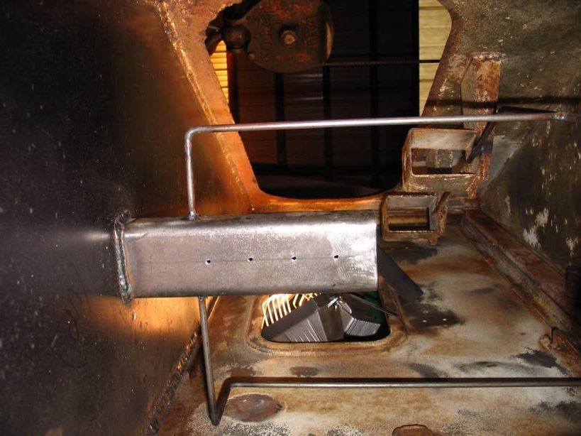
Image

Handrail refastened

Image

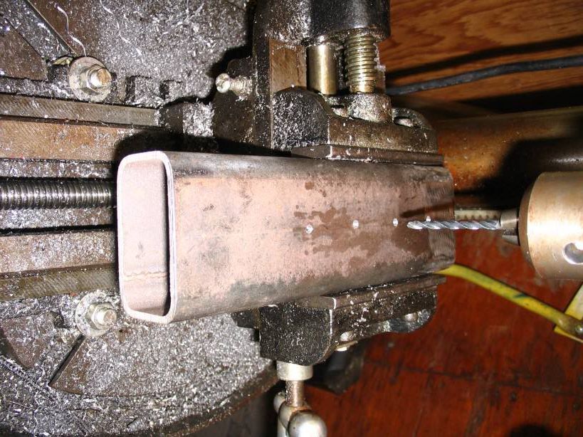
Mount for one of the steps was also replaced

Image

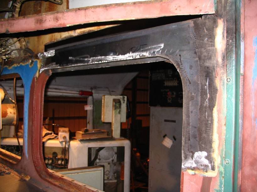
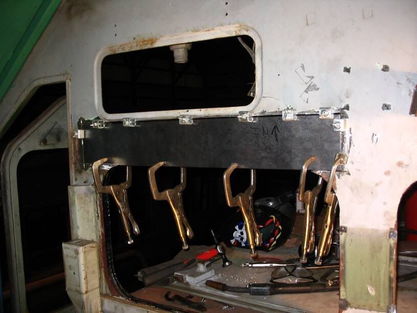
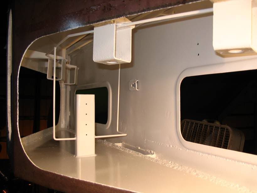
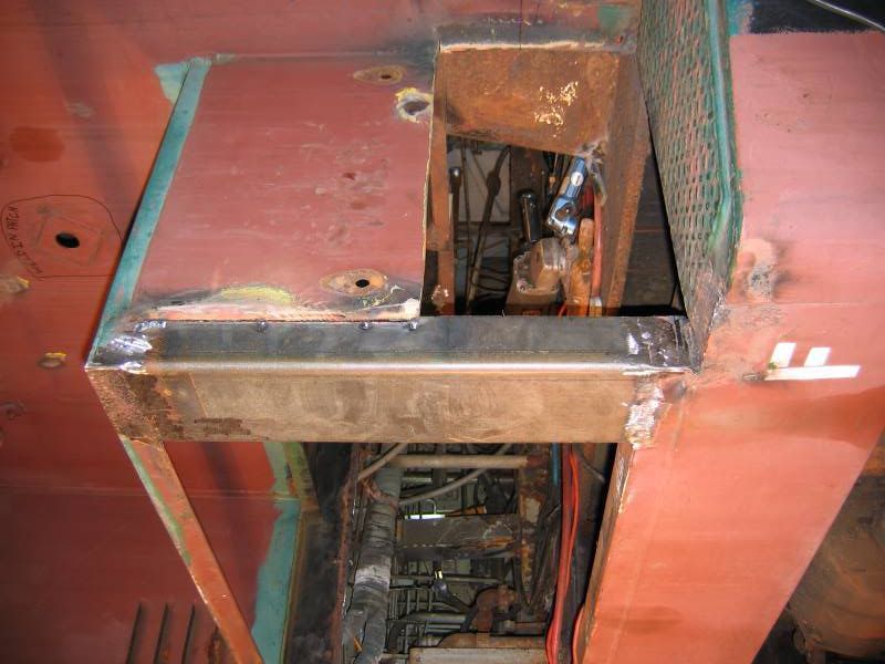
The new framework for the battery box was welded in place

Image

Image

Image

Image

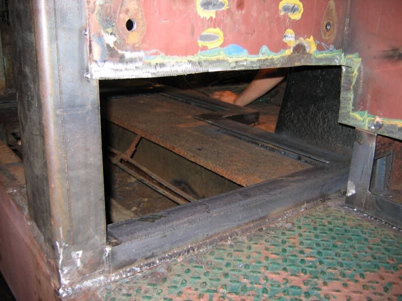
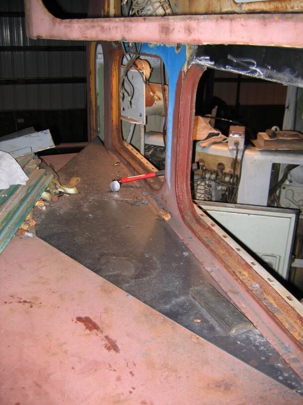
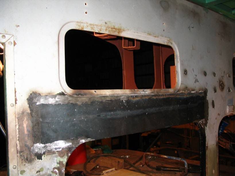
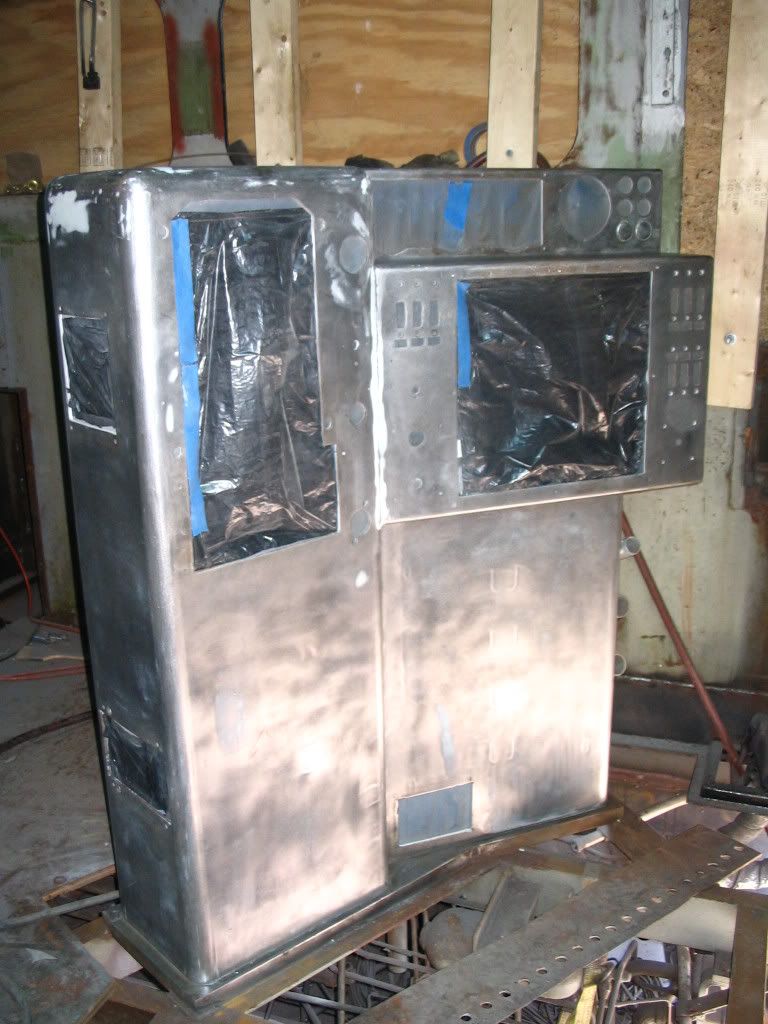
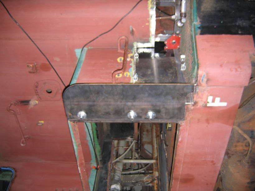
Next the new side sheets are installed

Image

Image

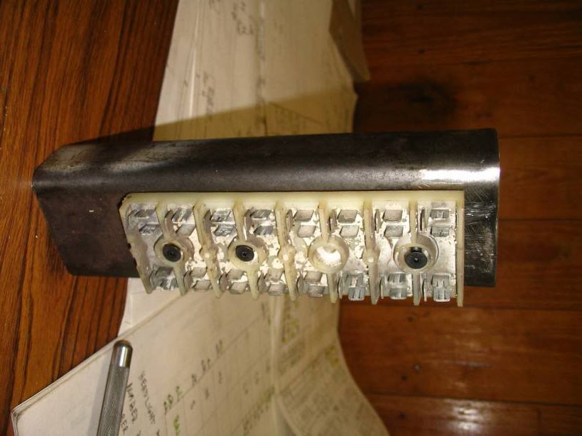
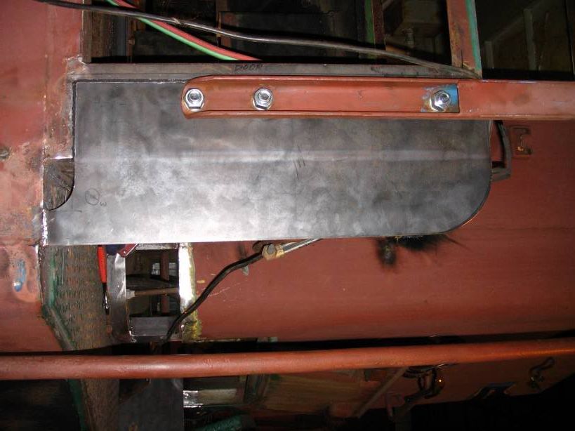
The new grate and acid deflector

Image

The new brackets for the spacers welded in

Image

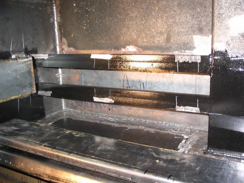
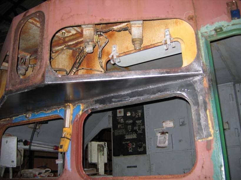
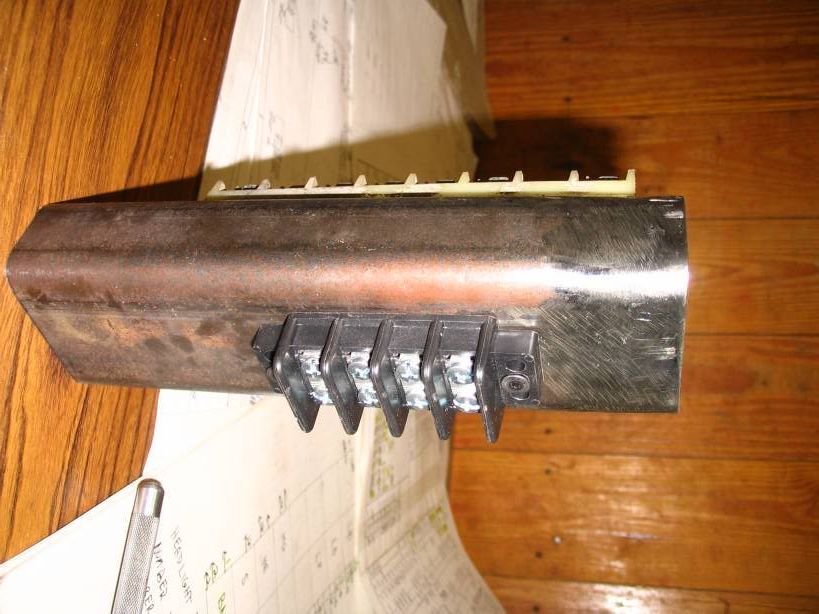
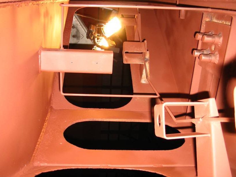
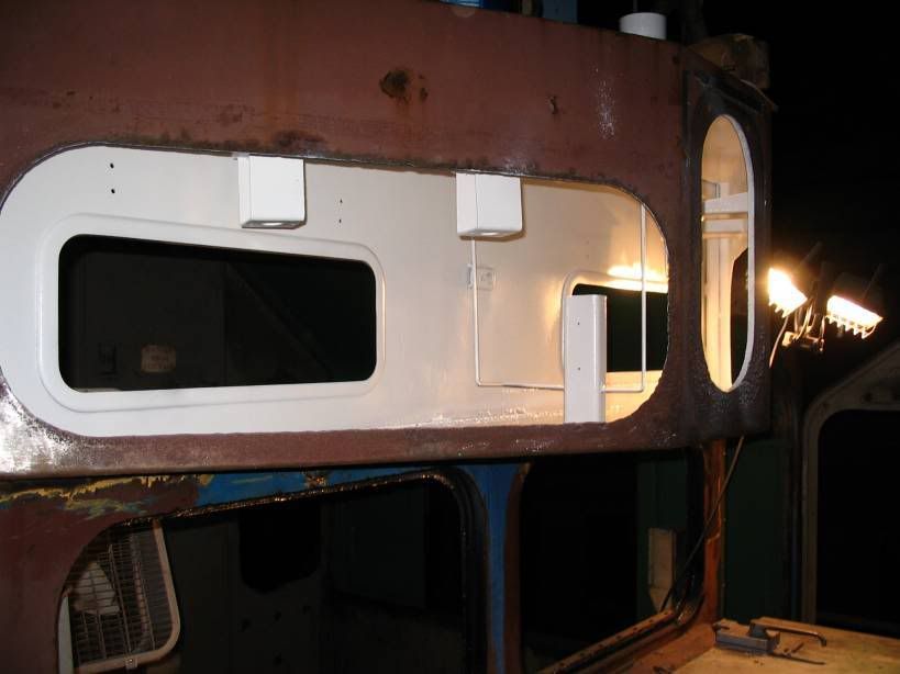
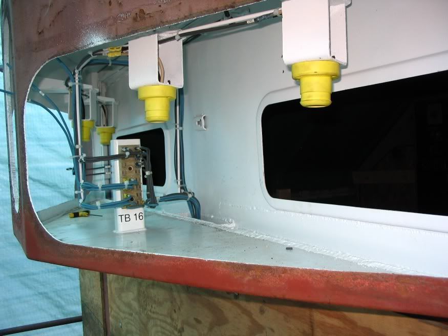
The spacers welded in place and new grate test fit

Image

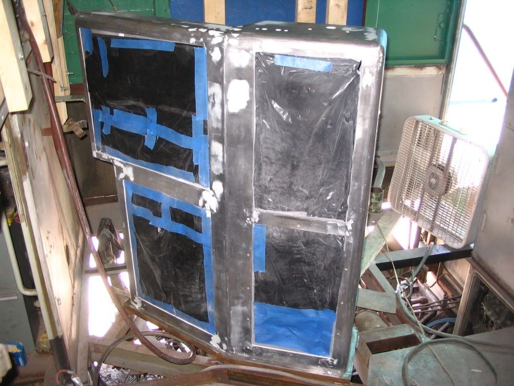
Straightening out the top edge

Image

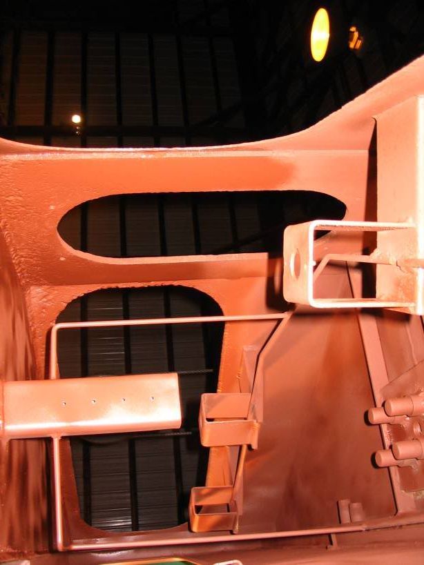
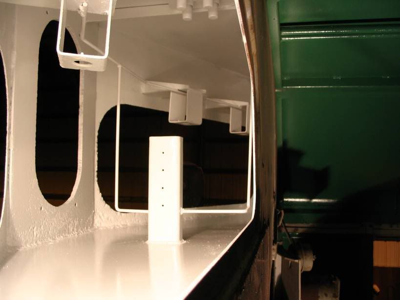
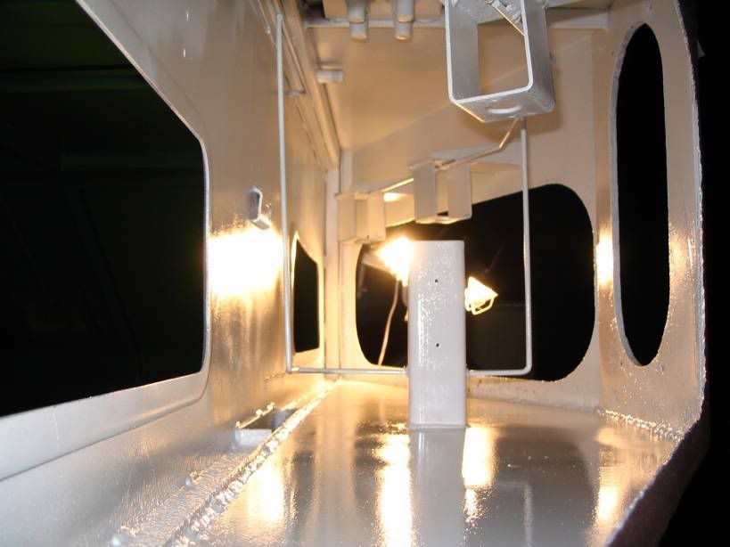
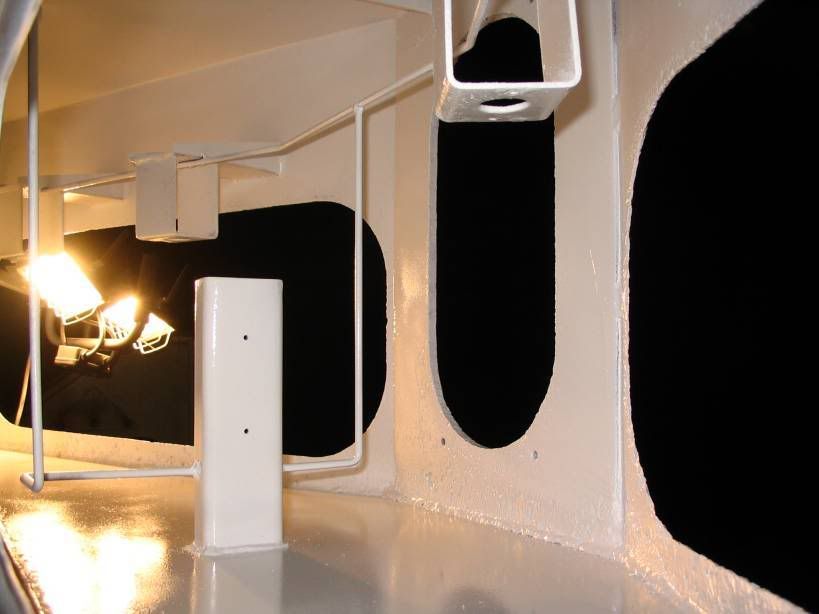
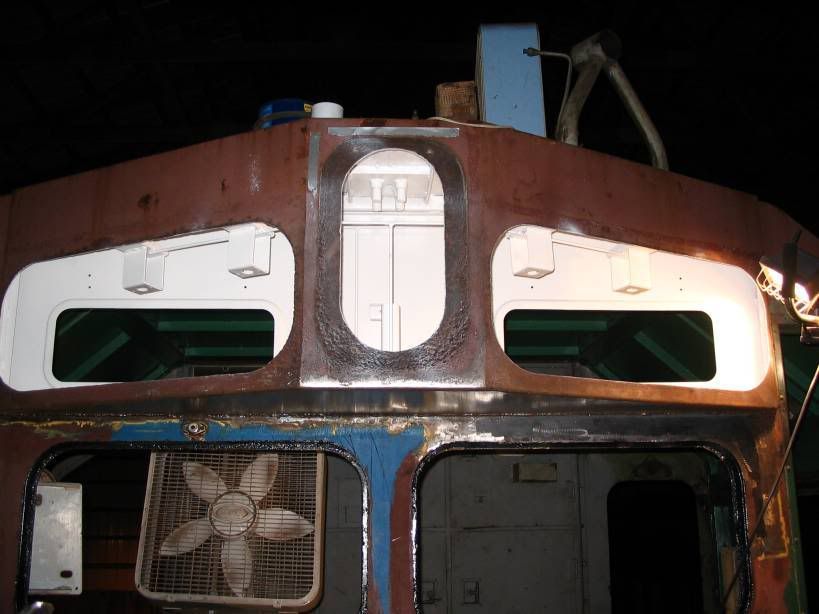
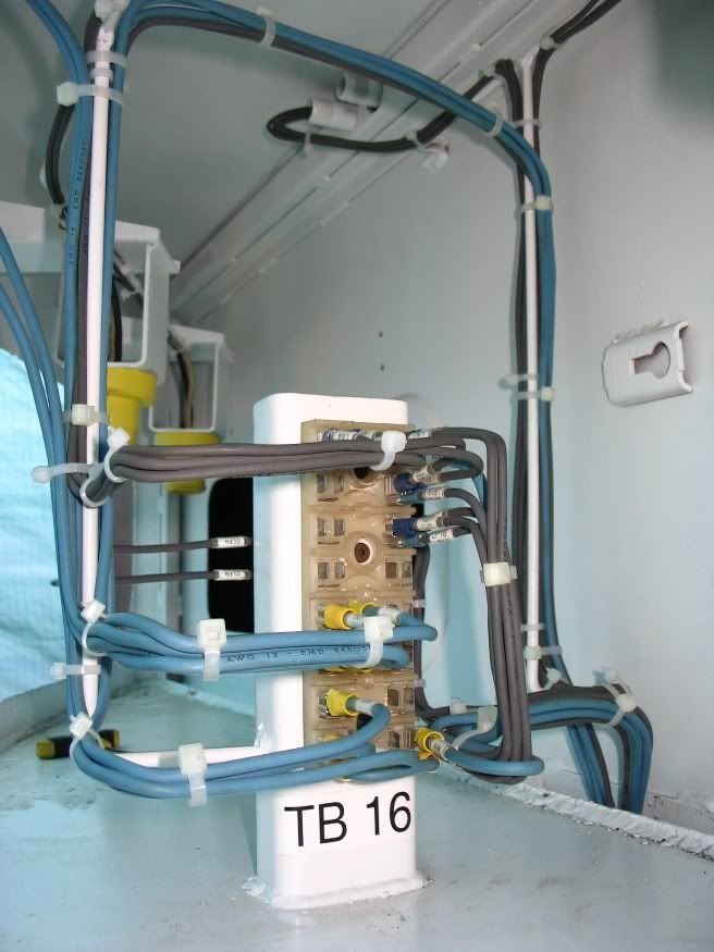
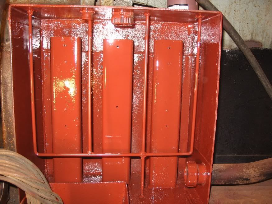
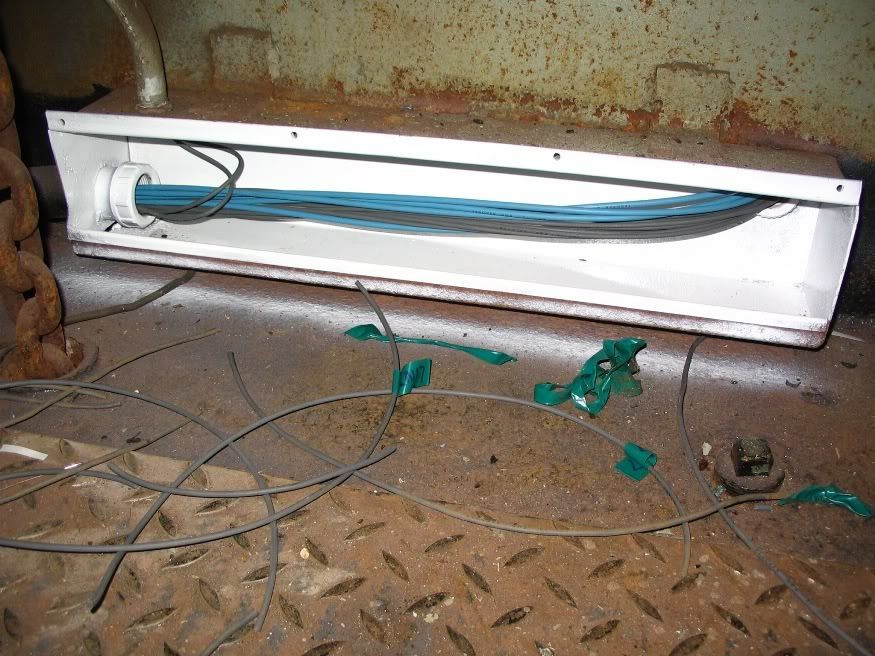
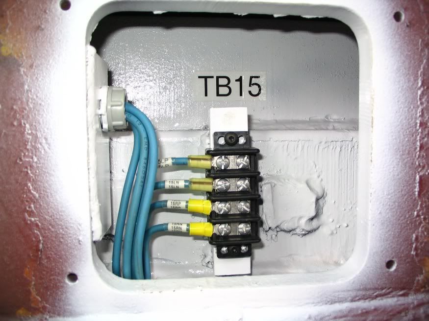
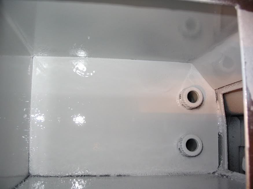
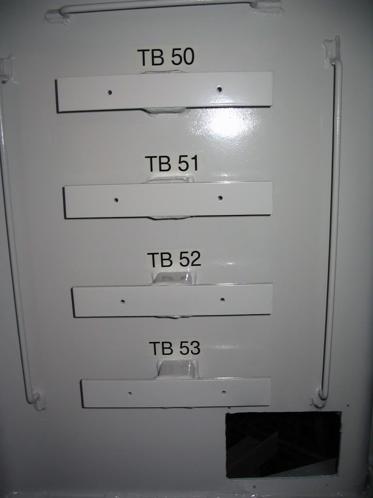
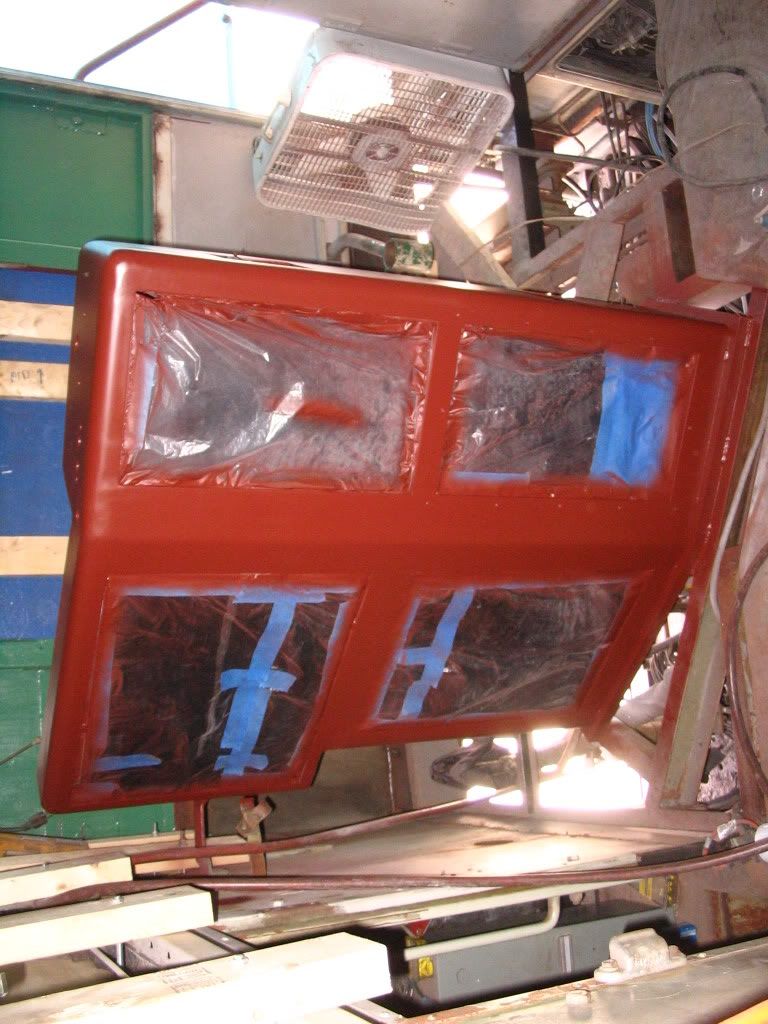
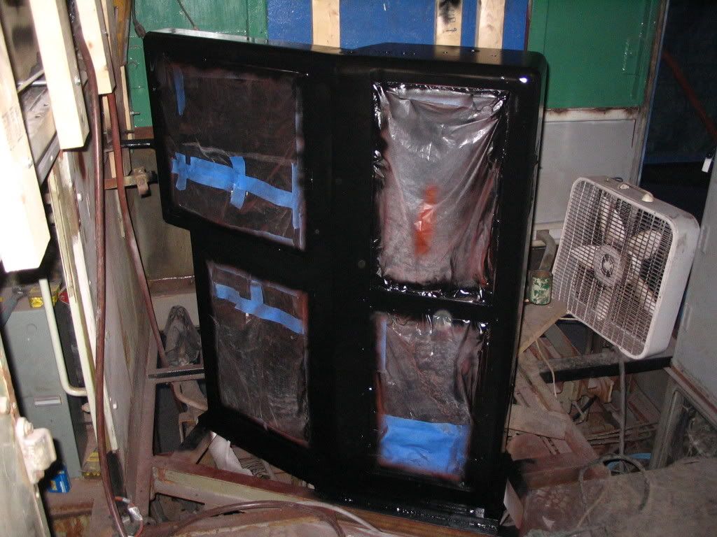
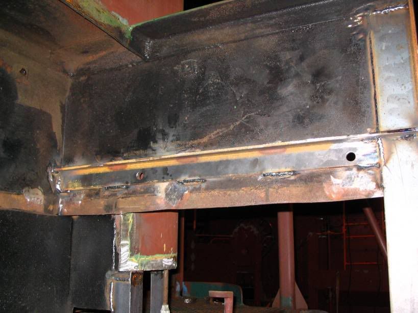
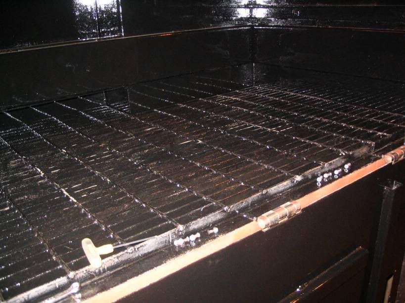
New grate in place all painted with acid resistant paint

Image

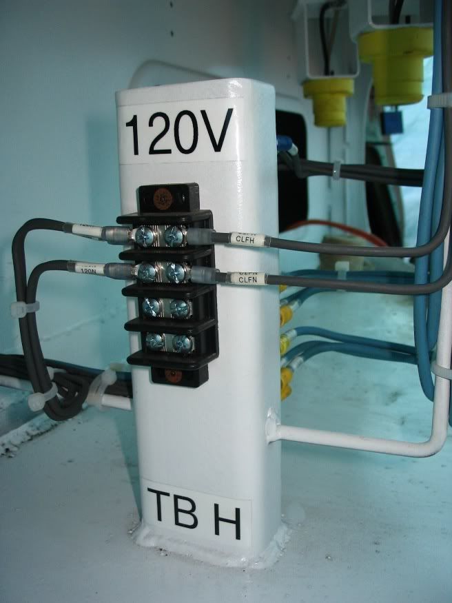
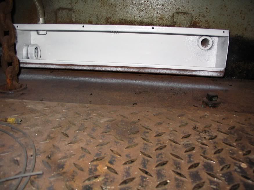
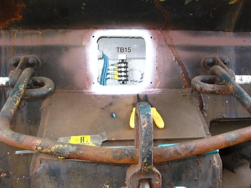
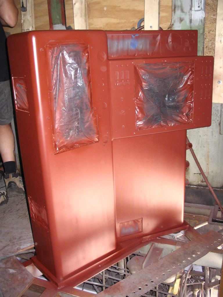
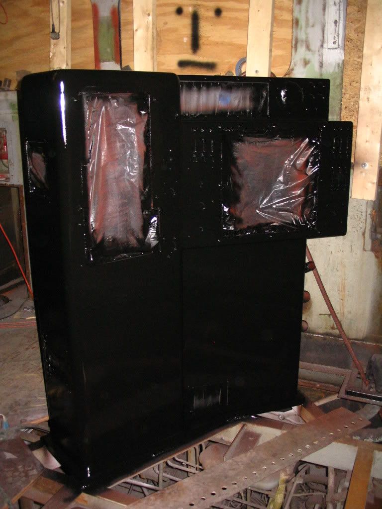
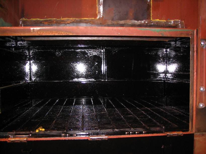
And the finished box

Image

 #531613  by scotty269
 
Very cool.

 #536647  by uhaul
 
Thank you for all the photographs. Thank you for restoring a unique Reading locomotive, and thank you for keeping the Reading alive. Looking quite forward to more news and photographs.

 #536794  by RDG Diesel
 
Hopfully this is what you were looking for

There are many different projects that have been done to 3640 so this is the rebuilding of the Number board Housing we decided to rebuild this area because of pit holes in the metal.

Image

After the Number board was removed this is what was on the inside

Image

After the bottom was cut out

Image

While the bottom was removed we took the opportunity to rebuild the front window frame

Image

The new frame

Image

New skin welded on top

Image

The new bottom for the housing

Image

Welded in place

Image

Another view

Image

The same view as the first photo

Image

The new inside wall fit into place

Image

And welded in place

Image

Smoothing out the welds

Image

A new terminal board mount had to be fabricated

Image

A picture of TB16

Image

Schematic Diagrams were made of all the wiring

Image

And Cross referenced with EMD Schematics unfortunately we do not have a set of schematics for 3640 so we have to make them from scratch

Image

TB16 test fit on its new mount

Image

TB H was also test fit

Image

After being test fit the new mount was welded into position and round stock was welded in place to tie off all the wiring

Image

The other side

Image

The entire housing was then primed

Image

Another view

Image

Head on

Image

The original angle again

Image

Then it all got finish painted

Image

Another view

Image

Another

Image

Head on

Image

Engineers side

Image

Original Angle

Image

After the finish painting everything got rewired

Image

We were lucky to find the original manufacture of the number board light sockets and buy brand new ones

Image

Another view of the rewired housing

Image

TB 16 again with its new wires in place

Image

A side view

Image

A view of the Engineers side

Image

TB H One of the things we are adding to 3640 is a 120V AC Lighting system to display the Locomotive after it restoration and to help with general maintenance

Image

Another view

Image

Image

After the feed wires were pulled to TB16

Image

The 120V also was fed

Image

A view of the whole thing

Image

Before

Image

And After

Image

Before TB16 could be finished the terminal boards that feed TB16 had to be rebuilt as well. Here are TB13 and TB14 before anything was done to them

Image

Next the old wiring was removed after all the wiring names were recorded a verified on the schematics

Image

This is the new 120V TB test fit on its new mount

Image

The new mount was welded in place also a new side was added to the box to seal the TB's better

Image

New round stock was added to secure the new wiring

Image

After the box was needle scaled and sanded it was primed

Image

Finish painted

Image

Next TB13, TB14 and TBN were mounted in place

Image

The wiring was pulled to feed TB16

Image

Then I got to wire it all up

Image

This is all the feed wires for TB16 terminated on the three terminal boards

Image

Finally all the feed wires for TB13 and TB14 were re-terminated till they can also get replaced

Image

The feed wires for TB17, TB15, TBNL, The forward sander and the nose lights were pulled next.

Image

All the wires pulled were then terminated

Image

This is the trough that the wires get pulled to after leaving TB13, TB14

Image

It was then primed after getting sanded

Image

Finish coated

Image

After the wires were pulled

Image

From the trough the forward sander got rewired

Image

After leaving the trough threw a conduit the rest of the wires go to the nose.

Image

The front walkway light socket was replaced and rewired. This is located just above the conduit.

Image

The four blue wires going out the bottom go to TB15. TB15 is added to feed the Ditch Lights.

These are all the pieces roughed in the wire raceway to the left and the mount for TB15 in the center.

Image

After everything was welded in place the entire area was needle scaled and primed.

Image

Then finish painted

Image

Image

Then the wires were pulled and TB15 was mounted and everything was terminated.

Image

Image

After leaving the nose the Wires end up at TB17 above the sandbox.

This is what the box looked like after it was sanded. The class lights and the nose light are all fed from TB17

Image

Primed up

Image

Finish painted

Image

New wires pulled

Image

This is the mounting plate for TB17

Image

Primed up

Image

Finish painted

Image

TB17 remounted

Image

Re-terminated wires

Image

The Physical drawing of TB17

Image

Also fed out of the box for TB17 is the new TBNL used for the 120V lighting

Image

Image

New wiring in place

Image

A new switch was added below the 74VDC switch for the existing Nose light for the new 120VAC lights

Image

Also added were two new 120VAC lights to the nose here is one roughed in

Image

The other

Image

TBNL with one of the New lights

Image

The new switch Box and the other new light

Image

One of the new lights

Image

Another View

Image

Image
 #543406  by uhaul
 
What about using fluorescent light bulbs instead of incandescents? Ceiling fan safe fluorescents are avalible, but is the extra cost of fluorescents not worth it?
 #543492  by RDG Diesel
 
The thought had crossed my mind but I know from some of my previous experiences with the fluorescent screw in bulbs is they really hate the cold and with the given drastic temperature changes a locomotive is constantly going through, add the fact the fixtures are sealed, and the impacts and vibrations that are part of locomotive operations. I decided to go with the good old tried and proved tungsten bulbs. Thats not to say we couldn't experiment with different bulbs on the locomotive in the future. I am sure someone will eventually develop a fluorescent screw in bulb that can with stand temperatures exceeding of 150 degrees and also work well at below 0 temperatures.
 #548373  by RDG Diesel
 
Some update photos of progress on 3640

As part of the recent rewiring the control stand and controller are getting a complete overhaul.

Here are TB50-53 this is where all 200 wires that connect to the control stand are terminated.

Image

Same angle taken after all the old wiring was removed as well as the terminal boards

Image

After getting a thorough cleaning and all the old paint removed the entire area was primed

Image

Then the finish coat was applied and the TB mounts labeled

Image


The same procedure was followed for all of the components in the control stand.

Image

After drawing new schematics everything was removed

Image

Cleaned then sanded

Image

and Primed

Image

Finish Painted

Image

The inside of the stand freshly painted. All of the air brake equipment and piping that goes to the control stand was also removed and all the old piping will be renewed.

Image

The outside of the control stand was then sanded down

Image

Image

Primed

Image

Image

Then finish coated

Image

Image

The Horn and Bell valves were taken apart and rebuilt

Image

Image

The controller was also taken completely apart and cleaned

Image

Image

The mechanical mechanism

Image

Image

The Bottom

Image

Image

Lots of pieces

Image

Image

Starting to go back together

Image

Starting to do all the rewiring

Image

Image

That is all for now hope to have some more soon
 #548409  by PARailWiz
 
These photos of the restoration project are great - they really illustrate the complexity of a restoration project, and the satisfaction that must come of doing such work.
 #548961  by jrevans
 
Thanks for the pictures and descriptions. I always wondered what was inside of the control stand and now I know.

What a neat mixture of mechanical and electronic elements in the design.

Great job as usual and I hope to see her in person someday.
 #553516  by N_DL640A
 
Great wiring job! Having done projects like this more than a few times (as my job, and not in restoration) I know how much work it really is! I'm impressed when someone takes the time to do a nice neat, proper job. Too many times I've seen in service locos with messy wiring jobs. Makes troubleshooting difficult!
The only tip I'll offer is that the single best investment I've ever made is in a ratcheting crimper. They make factory style crimps, and their ergonomic design cuts down on carpal tunnel while their compound action mechanisim producing highly reliable crimps at the same time!
 #553781  by RDG Diesel
 
Thanks for the compliments and the tips. I have always found a shacked in wiring job to be problematic in the long run either at work (I am an electrician) or in locomotives. With the amount of work that has been done to 3640 I feel the need to go the extra mile to see it done right and as a result I hope it will show and the unit will have a very long life after its restoration. I am hoping to have some updates within the next few weeks.
 #559836  by Otto Vondrak
 
Great pictures, thanks for sharing. You guys have done a great amount of work. I saw this unit in Hamburg last year and could not believe how much rot had to be replaced and rewelded. Keep up the good work!

-otto-
 #575887  by RDG Diesel
 
Here are some recent pictures of progress to 3640. We decided to remove the radiator hatch so we could sand and paint it properly.

"DINO" did the honors.

Getting "DINO" in position

Image

Rigging up the hatch

Image

starting to come out

Image

The hatch clearing the roof

Image

Starting to come out

Image

Clearing the side

Image

Getting lowered down

Image

Almost down

Image

A view of the hatch

Image

Re-positioning the hatch

Image

Image

Image

Image

Image

Next the hatch had to be flipped

Image

Image

Image

The hatch was then moved inside to begin restoration

Image

Image

Image

Needle scaling start

Image
 #601224  by RDG Diesel
 
Thanks for the complements! Currently we are documenting the entire electrical system so we can start re-wiring the unit. This is a rather large undertaking and takes quite a bit of time since we have to double check the prints we have due to the Modifications the engine has gotten over the years. I'm hoping to have some pics to put up soon however. So please stay tuned and thanks for the support of this project.